
The IEEE draft P370 standard described in this paper is in the IEEE review process, and is expected to be balloted and approved in 2019.
Most high frequency instruments such as vector network analyzers (VNAs) and time domain reflectometers (TDRs) can make very good measurements at the end of a coaxial interface. However, interconnects used in complex systems rarely have coaxial interfaces. The design and implementation of the fixtures used to characterize these devices can have a significant influence on the measured data, and, therefore, the observed characteristics of the device under test (DUT). The extent of these influences can potentially corrupt the measured data in ways that are not necessarily obvious to the user. Hence, some method is needed to ascertain the quality and usability of the measured data. The P370 standard committee was chartered with the task of solving these problems for the measurement of interconnects up to 50 GHz.
The P370 committee is comprised of approximately 60 members from 25 companies and universities. It has three task groups: Test Fixture Design Criteria, De-embedding Verification, and S-parameter Integrity and Validation. Task Group 1 is drafting guidelines for fixture design to ensure that devices measured with fixtures meeting the design criteria will produce accurate measurement data for the DUT after removing (“de-embedding”) the fixture effects. A design kit of reference structures has been designed and built for use in this process, and extensive measurements have been taken. TG1 has also published a sample software tool for performing the de-embedding process. Task Group 2 has developed an S-parameter library for the various structures and is working on the verification process for the de-embedded data when compared to the library data. Error data have been generated and evaluated. Task Group 3 is working on metrics and software tools for checking the integrity of the S-parameter data, including passivity, causality, and reciprocity. This paper previews the fixture design guidelines, reference structures, de-embedding techniques, and S parameter quality metrics and validation methods that is being developed as part of the P370 standard.
Major test equipment manufacturers and universities have participated in the committee’s work to date. The committee is making good progress, and the draft specification is currently in review. The target date for the draft to be ready for ballot vote in early 2019. Note that since the P370 standard is still an unapproved draft, any material included from it in this paper is subject to change.
Test Fixture Design Criteria
The quality of the measured data for a given fixture is highly dependent on the design of the fixture. The P370 standard establishes requirements for both the structures included in the fixture design and their electrical characteristics. The following structures are included in the draft standard:
- A 2x thru structure as shown in Figure 1 is required for measurement of fixture insertion loss and return loss.

Figure 1. 2x thru structure for measuring fixture insertion loss
There are a number of proposed requirements for the 2x thru structure that are intended to ensure usable, accurate measurements from this structure:
- The 2X thru shall be routed on the same PCB layer as the test fixture traces
- The 2X thru shall incorporate the same layer transitions and test point launch as the test fixture
- With the measurement reference plane set at the coaxial test point, the insertion loss of the 2X thru shall meet the requirements in Table 1.

Table 1. Minimum insertion loss for the 2x thru, by fixture class
2. A “dog leg” structure as shown in Figure 2 is required for measurement of fixture crosstalk in the case of a single-ended DUT. The purpose of these structures is to quantify the crosstalk induced by the test fixture, which is typically not considered in most de-embedding tools.
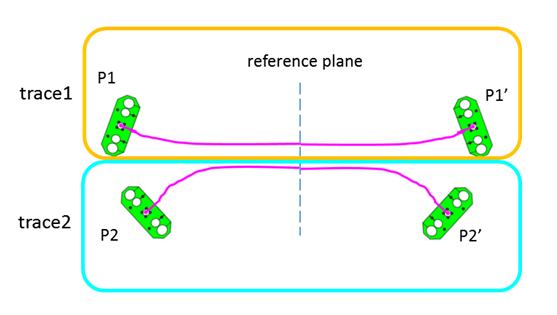
Figure 2. “Dogleg” structure for measuring single-ended fixture crosstalk
3. For differential DUTs, the “spiderleg” structure shown in Figure 3 is used.
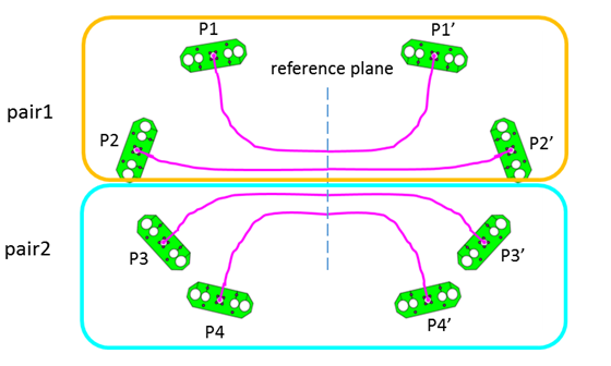
Figure 3 . “Spiderleg” structure for measuring fixture crosstalk for differential DUTs
4. An optional 1x reflect (Open or Short) structure as shown in Figure 4 is needed when the 1x-reflect algorithm is used for de-embedding. This is not the recommended algorithm when the 2x-thru is available. Therefore, it is just an informative specification, when a 2x-thru structure cannot be constructed in certain applications.
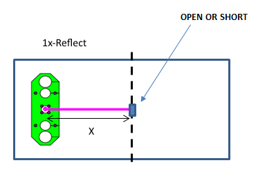
Figure 4. 1x reflect structure for fixture calibration
Verification Structures
Two structures are recommended to be included on PCB-based test fixtures to provide the data needed for verification of fixture de-embedding. These are the Line and Beatty structures. The line structure provides a qualitative approach to verify the de-embedding results, as the S-parameter of de-embedded line structure should follow the ideal behavior of a transmission line. The Beatty structure, described in [2] and shown in Figure 5, is a resonant network that provides insight into the fabrication process as well as the quality of the calibration. The increased line width creates a large low impedance discontinuity and a standing wave with resonances at frequencies defined by equation 1.
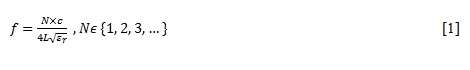
where
c is the speed of light,
L is the length 2X as shown in Figure 5.
εr is the effective dielectric constant (DK) of the PCB material

Figure 5. Physical design of a resonant Beatty structure
The insertion and return loss characteristics of such a structure are shown in Figure 6.
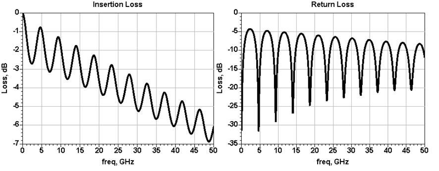 Figure 6. Insertion and return loss of a resonant Beatty structure
Fixture Electrical Requirements
The P370 standard proposes a number of requirements on the electrical performance of the fixtures described. The concept of compliance “classes” is introduced. These classes represent the quality of the electrical performance of a fixture relative to an ideal, or relative to the characteristics of the DUT. Fixtures with good electrical performance will result in better de-embedded DUT data than fixtures with poor electrical performance. Performance parameters included in the class definition include insertion loss, return loss, insertion and return loss separation, crosstalk, and differential to common mode conversion (in the case of a differential fixture). Table 2 summarizes the class definitions.
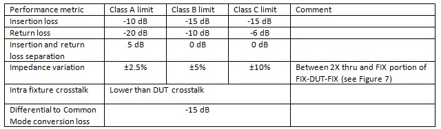
Table 2. Fixture Class definitions
Note that some de-embedding algorithms do not account for fixture crosstalk. A given fixture is described as Class A up to the maximum frequency at which it conforms to the Class A limit, Class B from that frequency to some other higher frequency at which the Class B limit is met, and Class C up to some other yet higher frequency at which it conforms to the Class C limit.
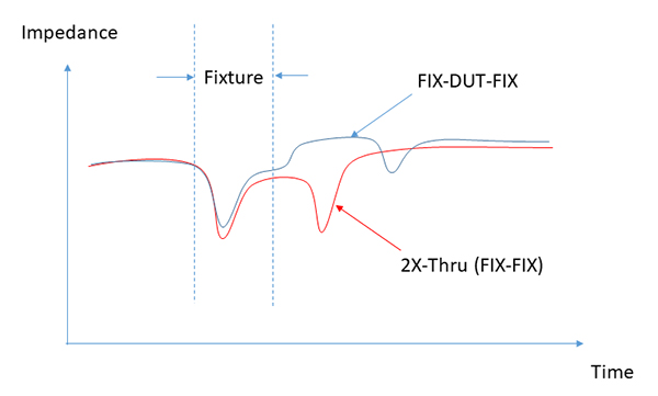
Figure 7. Fixture impedance variation
De-embedding methods
Traditional de-embedding has been done using the cascaded T matrix method described in [3]. This method uses cascaded matrices for the left fixture, DUT, and right fixture, as shown in Figure 8. The matrices are mathematically manipulated to remove the fixture contributions and produce the S-parameters of the DUT alone, as described in [3]. The draft P370 standard recommends use of what is being called the “Impedance-corrected 2X” method. This method, which is described in [4], eliminates the errors introduced when the fixture impedance varies from that of the test equipment, the structures used for the calibration, or even between the two halves of the fixture.
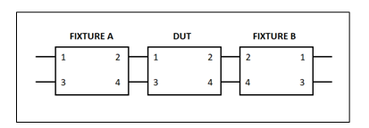
Figure 8. Cascaded FIX-DUT-FIX model
De-embedding Verification
Once the de-embedding method has been developed or selected, it is desirable to verify its accuracy prior to use. The P370 standard suggests three methods for verification of a de-embedding method:
- Use of synthesized libraries
- Use of Plug and Play test boards
- Use of user-manufactured demonstration boards
The first option allows the user to compare the de-embedded DUT data to those from synthesized data obtained from a field solver and/or circuit simulator. The P370 committee has generated a library of synthesized data for this purpose that includes coaxial launch connectors, single-ended and differential lead-in traces, and DUT structures. Structures using various combinations of design parameters such as dielectric constant, dielectric loss tangent, trace width, and trace spacing, are included, the result of which is varying line or pair impedance. Different launch via geometries are also included as shown in Figure 9, which are combined in various configurations with the sample DUTs shown in Figure 10. Due to the performance dependence on the via geometry, the combined test fixtures will have different electrical properties as described in Table 2. The synthesized S-parameter library can be used for EDA tool vendors to test the capability of their tools.
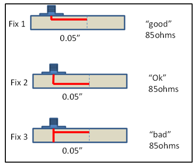
Figure 9. Launch via geometries included in the S-parameter library with different topologies
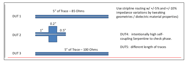
Figure 10. Sample DUTs included in the S-parameter library.
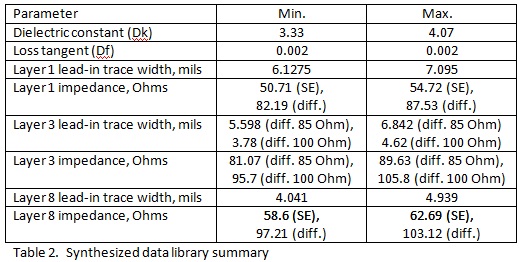
A summary of the contents of the S-parameter library is shown in Table 2.
Option 2, use of plug and play boards, enables the user to compare the results of the de-embedding process with results from direct measurements of a fixture and sample DUT components. In this case, coaxial connector adaptors are inserted between DUT and fixtures, so that a direct measurement of DUT (without de-embedding) is readily available, to be compared against the de-embedded results. The plug and play board set has been developed by the P370 committee, and the test data for it are available for use in verifying de-embedding algorithms. An example of an implementation of this board kit is shown in Figure 11.