
What is special about a material like PTFE that gives it such a low Dk and Df, while an epoxy has such a high Dk and Df? It is all about the chemical structure of the molecules and how they interact. Understanding the connection between chemistry and electrical properties is the starting place to engineer optimized materials for high-speed interconnects.
Electric and Magnetic Properties of Materials
Separated charges create an electric field. Moving charge (current) creates a magnetic field and an alternating current can create a propagating electromagnetic (EM) wave,consisting of coupled electric and magnetic fields. When in free space (vacuum), the energy stored in the electric field is proportional to the free space permittivity, ε0, with units of F/m (farads/meter).
All matter consists of atoms, with an electron cloud surrounding a positive nucleus. The atoms may form “polar” molecules with a permanent internal charge distribution (a dipole moment) or nonpolar molecules with symmetrically distributed charge. The electric field will “polarize” the material by displacing ions, rotating dipoles, stretching bonds between atoms or distorting the molecule’s electron cloud. Thus, an electric field stores more energy when acting upon any material than it does when interacting with nothing (free space) and the relative permittivity of any material, εR, is always greater than 1.0.
The energy stored in the magnetic field in free space is proportional to the free space permeability, μ0, with units of H/m (Henries/meter). Ignoring nuclear magnetic interactions, which are very weak, “paramagnetic” materials contain atoms with unpaired electrons such as platinum and aluminum. The interaction of paramagnetic materials with the magnetic field is very weak. The permeability relative to free space, μR, of platinum, for example, is 1.000026.1
“Ferromagnetic” materials (iron, nickel, and cobalt, rare earth elements, some ferrous metal and rare earth alloys, and ferrites) are a special case of paramagnetic materials where electron spins are preferentially aligned and are strongly affected by magnetic fields. Relative permeabilities of ferromagnetic substances range from 1.05 to > 105. However, most materials have no unpaired electrons and are “diamagnetic,” exhibiting a permeability lower than that of free space. Again, the interactions with a magnetic field are very weak. The μR of water, for example is 0.9999909.1 While there are numerous electrical engineering applications for ferromagnetic materials at both low and high frequencies, highspeed digital circuit laminates may be considered to be non-magnetic for engineering purposes, with the relative permeability, μR = 1.000.
In free space, the electric flux density vector, D (units of Joules/Volt-m2) resulting from an electric field, E is given by
In a material, the electric flux density, D, is equal to the energy storage in free space, E, and a contribution from the material’s polarization, P.
Most dielectrics, and certainly all high frequency laminates, are linear with respect to the polarization-field strength relation and the “electrical susceptibility,” χe' is defined by

Substituting Equation 3 into Equation 2 yields

where ε is the permittivity of the material and εR is the relative permittivity, also known as the “dielectric constant.”
Four Polarization Mechanisms
There are four polarization mechanisms. Space-charge polarization results from accumulation of charge at interfaces or separation of ions in solution. At low frequencies in an AC E-field, this can result in large separations and a large apparent εR. At higher frequencies, the ions cannot travel as far, and the apparent εR decreases significantly with increasing frequency. The effects of space charge polarization can be large. For instance, an “artificial dielectric” created by suspending 0.1 weight percent of conductive single-walled carbon nanotubes in a PTFE/silica composite exhibited a decrease in
measured “apparent” relative permittivity from 1000 to 10 as the frequency increased from 100 Hz to 1 KHz (see Figure 1). The permittivity of the silica/PTFE composite itself without the conductive nanotubes was 3.0. Above the range of KHz to 100 KHz, the field is alternating faster than the ions can respond, and space-charge polarization essentially freezes out. If a material does not have free charges, the space charge polarization mechanism does not occur.

Orientation polarization arises from rotating permanent dipoles from their equilibrium position. Recalling our freshman chemistry knowledge, when forming compounds, electronegative non-metals (for example, oxygen, chlorine, and fluorine) attract the electrons of electropositive metals and form ionic bonds that can result in large charge separation in solution. Sodium chloride, NaCl is a strongly ionic example. When reacting with less electronegative elements, such as hydrogen, carbon, and silicon, electronegative elements will form polar bonds with a permanent dipole moment, with water, H2O, as a classic example. When atoms of elements of similar electronegativity react, they form apolar bonds, which exhibit a low dipole moment. A carbon-hydrogen bond is an example of an apolar bond.
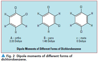
Molecular arrangement is also an important component of dipole formation. For instance, the electronegativity difference between oxygen and carbon is similar to the difference between oxygen and hydrogen. However, the polarity of carbon dioxide (CO2) and water (H2O) is very different. The 180° bond angle of CO2 results in a linear arrangement of the atoms; the molecule is symmetric and apolar. In the case of H2O, the bond angle is 109°, resulting in an asymmetric and highly polar molecule. Even exactly the same atoms arranged differently can result in a significant difference in polarity. For instance, ortho-dichlorobenzene (see Figure 2a) exhibits a polarity of 2.33 Debye, while meta-dichlorobenzene (see Figure 2b) exhibits polarity of 1.48 Debye, and para-dichlorobenzene (see Figure 2c) is completely apolar due to symmetry.
The orientation polarization mechanism is operative only when a material contains asymmetric polar bonds. The polar groups must also be mobile to contribute significantly to the permittivity of a material. Polarization orientation ceases to contribute to permittivity when the frequency of the electromagnetic field exceeds 1/τ, τ = the relaxation time or characteristic time for the polar group to return to its equilibrium position. This generally occurs in the frequency range of 107 to 1011 Hz. As will be discussed further, polymeric materials like the resins used in circuit substrates exhibit a very wide range of relaxation times.
Atomic polarization arises from the stretching of molecular bonds. It is operative in the 1011 to 1014 Hz range (infrared). Unlike ionic and orientation polarization, specific bond vibrations each exhibit a very narrow range of characteristic relaxation times. This forms the basis of infrared spectroscopy.
Electronic polarization arises from the EM field distorting the electron cloud associated with each atom and dominates dielectric properties beyond 1014 Hz, in the visible and ultraviolet radiation ranges. The refractive index of a material is essentially the √εR at the frequency of visible light. Refractive indices of solid materials at optical frequencies (not including aerogels) vary from about 1.3 to 2.65, implying permittivity values due to electronic polarization of about 1.7 to 7. At lower frequencies, the contribution of electronic polarization can be greater. Over the frequency range of 100 KHz to THz, the lowest permittivity values observed for solid non-polar materials is about 2.
Dielectric Loss
All of these polarization mechanisms result in a storage of electrical energy in the material which is “given back” to the EM field when the field is removed or reversed. However, the displacement of ions or electrons, rotation of dipoles, and vibration of bonds are all affected by friction on the atomic level. This leads to a loss of the EM field energy that is converted to heat. Both molecular friction and inertia also delay the polarization, leading to an “out of phase response.” Properties with a magnitude and phase (quantifying the “inphase” and “out-of-phase” or “storage” and “loss” portions) are conveniently represented as complex numbers. The complex permittivity, ε*, is given by
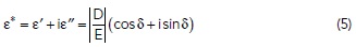
with the real quantity ε’ quantifies energy storage and the imaginary portion, ε” quantifies the loss, and δ is the phase angle. The loss tangent, tan δ = ε”/ ε’ (also called the dissipation factor) is approximately equal to the fraction of the EM energy that is dissipated per wavelength traveled.
The physical nature of all of these properties is nicely illustrated in Figure 3 (data from reference 2), comparing the εR and tanδ of water at 1.5°C and ice at 0°C over the frequency range of 100 KHz to 25 GHz. From 100 KHz to about 3 GHz, the εR of the water is approximately constant at a high value of 87, due to the rotating dipoles. As frequency approaches 1/τ, the field is changing faster than the water molecule can respond and the εR value drops to a value of about 15 at 25 GHz. The dissipation factor also passes through a maximum as the permittivity drops, as is predicted by Debye theory of the behavior of polar materials. Ice, of course, is made of exactly the same molecule, but dipole rotation is “frozen out,” since it is a crystalline solid. The εR value of ice is much lower and more stable than that of water, decreasing from about 4.8 to 3.2 over the five decade frequency range.

Engineering Materials
When designing a high-speed multilayer interconnect, a number of performance factors can be improved with a low permittivity, low loss dielectric material. Low dielectric loss, of course, contributes to lowering overall insertion loss, but it also leads to lower change in permittivity with frequency (dispersion) which decreases rise time degradation. Low permittivity shortens propagation delay. For a fixed impedance value, low permittivity dielectrics allow for wider traces, reducing conductor loss at a fixed layer thickness. Alternatively, at a fixed trace width, one can decrease layer thickness, thereby decreasing crosstalk and perhaps increasing layer count for a fixed overall board thickness.
At first glance, it would appear that to use non-polar dielectric materials would be obvious, and a large number of polymeric materials, including polyethylene, polystyrene, polypropylene, and PTFE could fill the bill. But as always, there are a number of engineering tradeoffs to be considered.
While the first printed circuits were developed by Paul Eisler prior to WWII,3 the industry took off in the 1950s with the commercial popularity of television and the transistor radio. These early circuits operated at low frequencies and had meager dimensional requirements, so the major requirements of the dielectric material was that it would adhere to copper foil and survive tin-lead soldering temperatures. Paper soaked in phenol-formaldehyde was made from low cost chemicals (it is widely used as plywood adhesive) and exhibited good high temperature resistance after curing. Phenolic resin is highly polar, with many asymmetric hydroxyl groups that lead to good adhesion to metals and metal oxides.
By the late 1960s, increasing circuit complexity and decreasing circuit feature sizes made dimensional stability an important laminate property. Circuit laminates are made by pressing the dielectric material between sheets of premade copper foil. In the case of thermoset materials, the resin first turns to a liquid and then reacts to form a solid network. In the case of thermoplastics, the resin melts and flows and then solidifies as it is cooled below its melting point. In both cases the dielectric becomes a solid at an elevated temperature.
Copper has a coefficient of thermal expansion (CTE) of about 17 ppm/°C. Solid polymeric materials exhibit CTE values of 100 to 200 ppm/°C. As the laminate cools, a “tug-of-war” develops between the foil and dielectric, building up stress that will be relieved by material movement once the copper is etched and the material is thermally cycled. E-glass (the “E” denoting a specific composition optimized for circuit laminates) fabric has an εR of 6.1 and tan δ of 0.006 at 10 GHz1 and CTE of about 5 ppm/°C. By impregnating glass fabric with either thermoset (such as epoxy) or thermoplastic (such as PTFE), a composite material is formed that can be CTEmatched to the copper foil.
Epoxy resins exhibit a εR of about 4.0 at 100 KHz to 3.1 and tan δ of 0.015 to 0.02 at 10 GHz2. In 1968, NEMA established the FR-4 grade of brominated flame retardant, epoxy-glass fabric composite laminates that continue to be widely used in electronic circuitry today. The glass fabric content in FR-4 is in the range of 30 to 60 weight percent, and the composite exhibits permittivity values of 3.9 to 4.7. Epoxy resin, not surprisingly based on its name, contains oxygen, and epoxies are polar compounds. The polarity leads to natural good adhesion to copper foils, but the higher dielectric loss limits their use at higher frequencies. The higher tanδ values of epoxies are indicative of the fact that, due to the asymmetric polarity and chain segment mobility, the dipolar mechanism is contributing significantly to the permittivity.
Glass fabric composites are by nature anisotropic, with the essentially continuous glass fibers leading to low inplane CTE, but offering little CTE reduction in the z-axis, or through-plane direction. We recall that thermosetting resins, once they have cured, will never flow again, but they do exhibit a glass transition temperature, Tg. On the molecular level, the Tg is the temperature at which the material begins to change from a disordered non-crystalline solid (a “glass”) to a rubber.
From the polymer scientist’s point of view, the polymer chain mobility increases markedly. While below Tg, individual main chain atoms can rotate, above Tg cooperative motion of groups of the main chain atoms can occur. Below Tg, many thermosets exhibit CTE values of around 50 ppm/°C while above Tg, the CTE may be 250 ppm/°C or higher. With the higher temperature necessary for lead-free solder, this can lead to the rupture of the copper barrels of plated through holes. Even if they survive to soldering step, high z-axis CTE can lead to copper fatigue and PTFE failure when thermal cycled long-term. Additionally, a polar compound can exhibit a significant increase in εR and tan δ above the Tg due to the increase in chain mobility. The original FR-4 grade exhibited a Tg of about 125°C. High performance grades of epoxy are now available with Tg values of over 180°C.
An alternative way to lower the z-axis CTE of a circuit laminate is to employ a ceramic filler either instead of, or in addition to glass fabric. Fused amorphous silica exhibits an εR of 3.78 and tan δ of 0.00017 at 10 GHz2 and a phenomenally low CTE of 0.6 ppm/°C. Composites made with spherical fused silica filler are nearly perfectly isotropic in both CTE and dielectric properties. Composites made with irregularly shaped ground fused silica or in combination with glass fabric, while not perfect, are considerably more isotropic than unfilled glass fabric reinforced materials. Since the εR and tan δ of fused silica are substantially lower than E-glass, substituting the filler for the fabric leads to lower permittivity and lower loss composites as well. The extremely low tan δ indicates that only electronic polarization is contributing to the permittivity of fused silica.
PTFE Composites
As mentioned above, many common non-polar thermoplastic hydrocarbon polymers exhibit εR values of less than 2.4 and tan δ values of less than 0.002, including polyethylene (sandwich bags), polystyrene (foam drink cups and packaging), and polypropylene (yogurt containers). However, all of these materials melt or exhibit a Tg far below lead-free soldering temperatures. Polytetrafluoroethylene, PTFE, however, exhibits a melting point of 327°C, well above even lead-free soldering requirements. While the carbonfluorine bond is highly polar, the symmetry of the repeat unit, -CF2CF2-, causes it to have very low polarity. PTFE exhibits an εR = 2.08 and tan δ of 0.00037 at 10 GHz2. Clearly PTFE interacts with an EM field solely though the electronic polarization mechanism, leading to its very low permittivity and loss values.
PTFE composite laminates have been used in microwave frequency applications. The tables of dielectric properties2 contains data up to 10 GHz for “Dilecto GB-112T laminate” from Continental Diamond Fiber, a company acquired by Arlon which joined with Rogers Corp. in 2015.
In more recent years, Rogers has optimized PTFE composite laminate technology for high performance digital applications with the introduction of XtremeSpeed™ RO1200™ series laminates. These materials are formulated with a fused silica filled-PTFE resin coated on spread glass fabric and exhibit an εR = 3.0 and tan δ < 0.0017 at 10 GHz.
The glass fabric content is minimized for lowest possible permittivity and loss and spread glass is used to minimize signal skew. In addition to reducing the permittivity and loss by replacing glass fabric with fused silica, the silica results in a z-axis CTE of 30 ppm/°C and also gives the material a very low temperature coefficient of permittivity. The εR increases by only 0.25 percent from −50°C to +150°C, compared to about 8 percent for epoxy-based composites. XtremeSpeed RO1200 series laminates combine the surface smoothness of a non-woven PTFE laminate, for finer line etching tolerances, with the rigidity of a woven-glass PTFE laminate. These materials can be fabricated into multilayer printed circuit boards using standard PTFE circuit board processing techniques. The standard thicknesses are 0.010 and 0.003 to 0.008 in 0.001 in. increments. In spite of the low polarity of the PTFE resin, good adhesion to smooth copper foil can be obtained by optimizing the strength and ductility of the composite. The “RA” (rolled) foil used on XtremeSpeed RO1200 series laminates, for instance, has been shown to be “electrically smooth” up to 110 GHz.3 This results in the lowest loss achievable in a multilayer circuit board using conventional technology.
Thermoset materials that process more similarly to FR-4 can often result in lower costs when the ultimate performance is not required. Designing thermoset laminates for high-speed digital applications relies on the same basic concepts of utilizing low polarity materials for lower permittivity and loss and finding engineering solutions to the drawbacks of low polarity. Rogers RO4000® series high-frequency laminates were introduced commercially more than 20 years ago. The polymer binder was a mixture of hydrocarbon polymers containing reactive double bonds and initiators for polymerization that would add as little polarity to the matrix as possible. Fused silica was used to reduce CTE in all three axes and minimize the higher permittivity/higher loss E-glass content. Since the cross-linked hydrocarbon resin-filler system is much more rigid and less ductile than the PTFE composite, the original products relied on high profile copper foil. For many years now, these laminates have been widely used in telecommunications base station amplifiers. At cell phone frequencies of lower than 2.6 GHz and with fairly large circuit features, the high profile copper foil did not result in any drawbacks.
For more information on the chemistry and physics of the behavior of dielectric materials, the author highly recommends A. von Hipple’s Dielectric Materials and Applications.2 Though published more than 60 years ago, the information is not out-of-date, is accessible to anyone with a technical background, and the book is available from Amazon. In addition, there are 125 pages of permittivity and loss data versus frequency and temperature for nearly every material imaginable that existed in 1954.
Article was published in the SIJ July 2019 Print Issue, Technical Feature: Page 22.
References
1. http://hyperphysics.phy-astr.gsu.edu/hbase/Tables/magprop.html.
2. A. R. Von Hipple, “Dielectric Materials and Applications,” The Technology Press of MIT and J. Wiley & Sons, New York, 1958.
3. “The Printed Circuit Board of Paul Eisler: History,” https://history-computer.com/ModernComputer/Basis/printed_board.html.
4. A. F. Horn III, P. A. LaFrance, C. J. Caisse, J. P. Coonrod, and B. B. Fitts, “Effect of Conductor Profile Structure on Propagation in Transmission Lines,” DesignCon 2016, January 19-21, 2016.