
Do corners in traces on circuit boards cause reflections? Of course, they do. Do the reflections cause problems and should you worry?….it depends.
Of course, corners cause reflections
The reflection from corners in circuit board traces is the poster child for signal integrity analysis. This is an example of how just the physical design of the layout influences the signals. As simple and common a feature in a circuit board trace as a 90-degree corner can impact the signal quality.
Why do 90-degree bends influence the signal? It has nothing to do with “electrons accelerating around the corner.” It is as simple as the excess metal in a 90-degree bend as compared to the width of the trace if it were to remain constant (as with a rounded bend).
The excess metal adds excess capacitance, and this capacitive discontinuity causes a reflection. How big an impact a corner has depends on two factors: the rise time of the incident signal and how much excess capacitance is in the corner.
Yuriy Shlepnev, president of Simberian Software recently posted a very nice review paper on his web site comparing the measured and simulated response from a 90 degree bend in a trace on a board. The board was designed and manufactured by Jose Moreira of Advantest. The simulated responses were calculated with the Simbeor 3D EM simulator. Figure 1 is from this paper showing the time domain reflectometer (TDR) response from the 20.5 mil wide, 50 ohm line, built on Rogers 4350B substrate. The TDR rise time simulated and measured was about 20 psec. It shows an impedance dip of about 5 ohms for this rise time. It should be noted that the impedance scale is 1.25 ohms/div. A shorter rise time would result in a larger impedance dip. A longer rise time in the TDR response would result in a smaller impedance dip for the same corner feature.
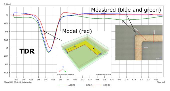
Figure 1 From Yuriy Shlepnev's paper, showing the test structure, the measured TDR response, and the simulated response. The two measured responses are different traces. Courtesy of Yuriy Shlepnev.
This is yet another example showing that a 90-degree bend causes a capacitive reflection which is exactly what is predicted using the Simbeor 3D EM simulation.
The insertion and return loss show the impact from a corner in the 20.5 mil wide trace over a wide frequency range. The measured and simulated S-parameter responses are shown in Figure 2.
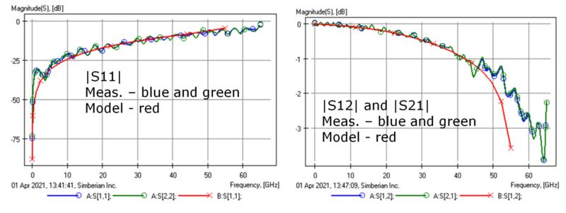
Figure 2 From Yuriy Shlepnev's paper showing the measured and simulated insertion and return loss for a 20.5 mi wide trace with a 90-degree corner. The insertion loss also has some of the losses from the residual trace left after de-embedding. Courtesy of Yuriy Shlepnev.
But, are corners a problem?
If we use the condition of a return loss below -15 dB as insignificant, this 20.5 mil wide trace is transparent below 25 GHz. This does not mean corners only play a role above 25 GHz. It depends on the line width. Sometimes the only way to know when the presence of a corner(s) will affect signals to the extent they should be mitigated is by performing a simulation. But, a 3D EM simulator should not always be the first tool you grab to estimate the impact from a corner. “Sometimes an okay answer NOW! is better than a good answer late.”
If an otherwise uniform trace were to make a 90 deg turn with a constant line width, as in a rounded bend, there would be no excess capacitance and very little impact from the turn. But a corner has more conductor than a rounded bend. The entire corner is literally in the shape of a square, with a dimension of a line width on each side. Not all of it is excess, however. The excess capacitance in a corner is roughly about ½ of the square making up the corner.
A very simple approximation can be used to estimate the excess capacitance in a corner. This capacitance is equivalent to the capacitance of about ½ square’s worth of capacitance, which is roughly,
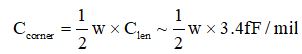
Where
Ccorner = the excess capacitance in a corner
w = the line width of the 50 ohm transmission line
Clen = 3.4 fF/mil is the capacitance per length in a 50 ohm line with a Dk = 4
The capacitance per length in any uniform, 50 ohm transmission line fabricated in a laminate with a dielectric constant of 4 is 3.4 pF/inch or 3.4 fF/mil. This is true if the trace is 1 mil wide, or 1 inch wide, as long as it is a 50 ohm impedance line.
For a 20 mil wide trace, the excess capacitance in a corner is 0.5 x 3.4 fF/mil x 20 mils = 34 fF. We can simulate the TDR response from a 34 fF capacitor with a 20 psec rise time signal (or any rise time) and the return loss. In the TDR simulation, a 34 fF ideal capacitor is added in shunt to the middle of an otherwise ideal, uniform 50 ohm transmission line. Figure 3 shows these simple simulations.
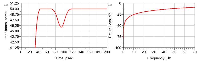
Figure 3 Simulated TDR and return loss of a 34 fF capacitor in a 50 ohm line. Scales are identical to the ones on the Simbeor plot.
The TDR response of the 34 fF capacitor and the return loss match the 3D EM simulation extremely well. A corner behaves exactly like a small excess capacitor. The capacitance in a corner depends on the line width of the 50 ohm line and is about 1.7 fF/mil of line width. This amount of excess capacitance can be used in any circuit simulator to evaluate the impact of a corner in any application.
For example, while one corner may not produce a very noticeable effect at a specific rise time, multiple, periodically spaced corners can create a Block Wave resonance and show an enhanced return loss and a dip in the insertion loss at the Block Wave resonant frequency. This is easily simulated using a uniform transmission line periodically loaded by small excess capacitors.
Why does this question invoke an emotional response?
Ask older microwave engineers about 90-degree bends in circuit board traces and they will tell you horror stories about the problems they had in some design they did 30 years ago that taught them to avoid bends.
Ask layout engineers about 90-degree bends in traces and they will tell you about how the electrons accelerate around the bend, give off radiation from the tip, and distort the signals; not to mention the hardware engineers they work with swearing to them that corners should be avoided.
And on the other side are engineers who say the impact from a corner is negligible and is a distraction. They designed and built hundreds of boards with 90-degree corners and they never had a problem. All these engineers saying corners are a problem is all noise and they don’t know what they are talking about.
This situation is similar to the tale of the five blind monks and the elephant. Each monk who feels a different piece of the elephant is absolutely convinced the elephant is a wall or a snake or a tree trunk or a fan. How can so many engineers (monks), looking at the same corner (elephant) have such widely different opinions? How should an engineer make their own decision as to whether it is ok to use corners or should all bends be rounded in their next design?
Should corners be avoided in your design has only one answer, “…it depends.” And the way we answer “it depends” questions is to putt in the numbers. This is how we see the whole elephant.
If you are designing a 2-layer microwave board with a 60 mil thick substrate, your line width for 50 ohms will be on the order of 120 mils. The excess capacitance in a corner is 1.7 fF/mil x 120 mils = 0.2 pF. If you are designing a multilayer board and line widths are 5 mil, a corner has a capacitance of about 1.7 fF/mil x 5 mils = 8.5 fF. At what bandwidth do these excess capacitances begin to impact signal performance? We can put in the numbers.
The return loss is a useful parameter to describe when reflections begin to affect the transmitted signal at the receiver. If the return loss is less than -15 dB, the impact on insertion loss is less than 0.1 dB, or negligible. Figure 4 shows the simulated return loss for corners in traces of 120 mils, 20 mils, and 5 mils wide.
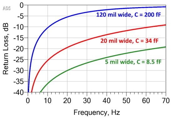
Figure 4 The simulated return loss from three different value capacitors corresponding to the excess capacitance in a corner for three different line width 50-ohm traces.
If your interconnect traces are 120 mils wide, a 90-degree corner might have a noticeable impact at 5 GHz. At 10 GHz, the return loss for just one corner is -10 dB. This will definitely impact the insertion loss. And at 20 GHz, with a -5 dB return loss, a corner can completely destroy a signal on your interconnect. Avoid corners at all cost or your design is ruined. This elephant is a wall.
But if your interconnect trace is 5 mils wide, you will not see an impact from a corner at bandwidths even as high as 70 GHz. Don’t worry about corners, there are far more important problems to deal with. This elephant is a fan.
Conclusion
Do corners cause reflections? Absolutely. You can measure it, you can simulate it, you can predict it. Should you be worried and avoid corners? It depends. If your design is sensitive to an excess capacitance of 1.7 fF/mil x w for 50 ohm lines, per corner, then worry about corners and consider a mitigation plan like mitered or rounded bends. If there is a cost impact to your decision, you might consider a more accurate prediction using a 3D EM field solver.
By putting in the numbers, even by using a simple estimate, we can learn to see the entire elephant and decide for ourselves what the piece we have in front of us really looks like.