
Introduction
In the early days of their engineering careers, some may have encountered power integrity issues within IC voltage supply during laboratory work. At that time, most engineers held the belief that increasing the decoupling capacitors, each possessing distinct impedance-frequency characteristics, would inevitably lead to an improvement in the power distribution network (PDN). Since capacitors in a parallel setup follow the path of least impedance, we believed that adding diverse capacitors would help us find the right match for the power network’s health. It seemed logical that we could select the appropriate capacitor for our desired PDN outcome. The rationale behind this strategy was difficult to dispute - how could it yield anything other than enhancement?
This method appeared promising in its potential to uncover the precise capacitor needed to achieve the desired impedance for the PDN.
However, when actually used, it showed differences. While it worked well in some situations, it unexpectedly made power-related issues worse in others, resulting in stronger ripples within the IC voltage supply.
LC Resonators
For the understanding of the whole picture, we have to discuss about LC resonators, formed by connecting an inductor (L) and a capacitor (C) in parallel, add another layer of complexity to the realm of decoupling capacitors. These circuits are known for their ability to resonate at specific frequencies.
In an LC parallel resonant circuit, something interesting happens at the resonant frequency. The way the inductance and capacitance interact creates a specific relationship between them, which affects the equivalent resistance. This interaction leads to different behaviors at different frequencies.
In lower frequencies than the resonant frequency, the circuit behaves in a way that's mostly influenced by the inductor. As a result, the inductive part of the circuit is more dominant than the capacitive part.
Once the resonant frequency is reached, the balance shifts, and the circuit starts behaving more like a capacitor. At this point, the capacitive part becomes stronger than the inductive part, and this results in the circuit having lower impedance, which allows energy to flow through more easily.
To see a visual representation of these behaviors, please see Figure 1, where these different profiles are shown graphically.
The Whole Picture
The assumption made in the introduction is inaccurate, as it oversimplifies the scenario by neglecting the influence of phase and inductance. It is not merely a matter of parallel resistors or parallel impedances with identical phases.
Analysis
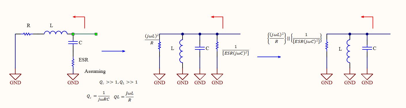
Let us assume that our circuit, up to the point of analysis, comprises resistance and inductance in series. This assumption is reasonable, as we have excluded the capacitive component from our frequency range analysis, and the inductance has begun to exert its influence, just to clarify, with these assumptions, our analysis applies to any part of the circuit between the last decoupling capacitor (where it starts behaving like an inductor within our specified frequency range) and the IC. Now, the models with and without the capacitor are depicted in Figure 2.
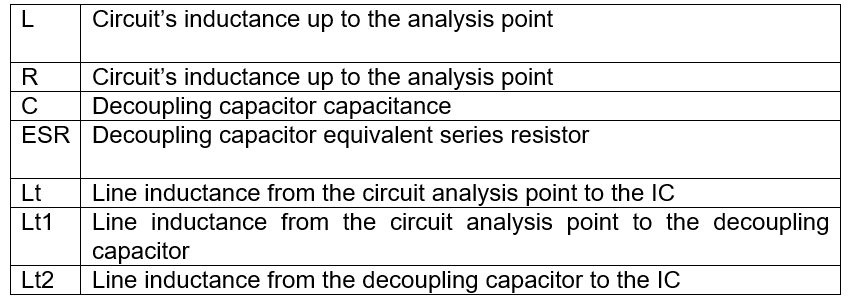
Parameters:
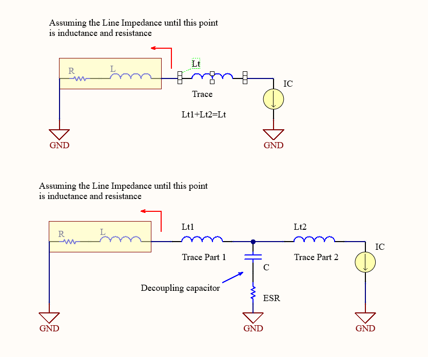
Let us proceed to calculate the impedance of the circuit in the absence of a decoupling capacitor, as shown in Figure 3.
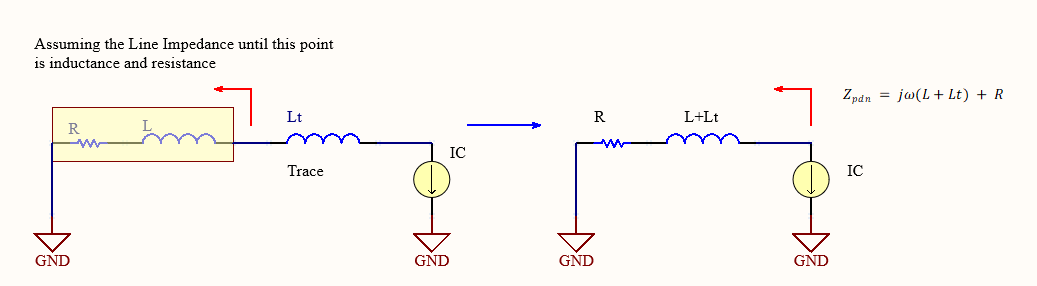 Figure 3. Circuit without decoupling capacitor.
Now, we shall proceed with the impedance calculation for the circuit that includes a decoupling capacitor, as shown in Figures 4, 5, 6, 7:
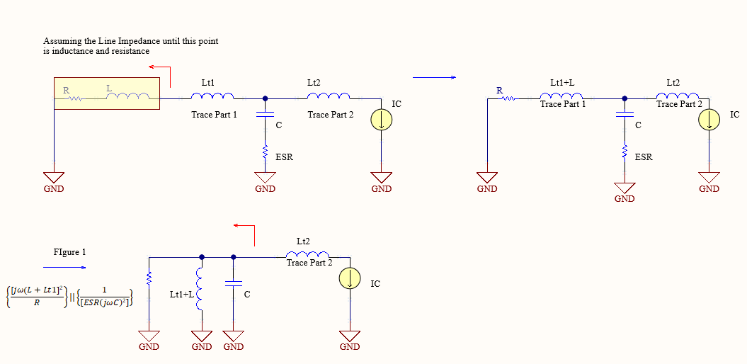 Figure 4. Equivalent Circuit.
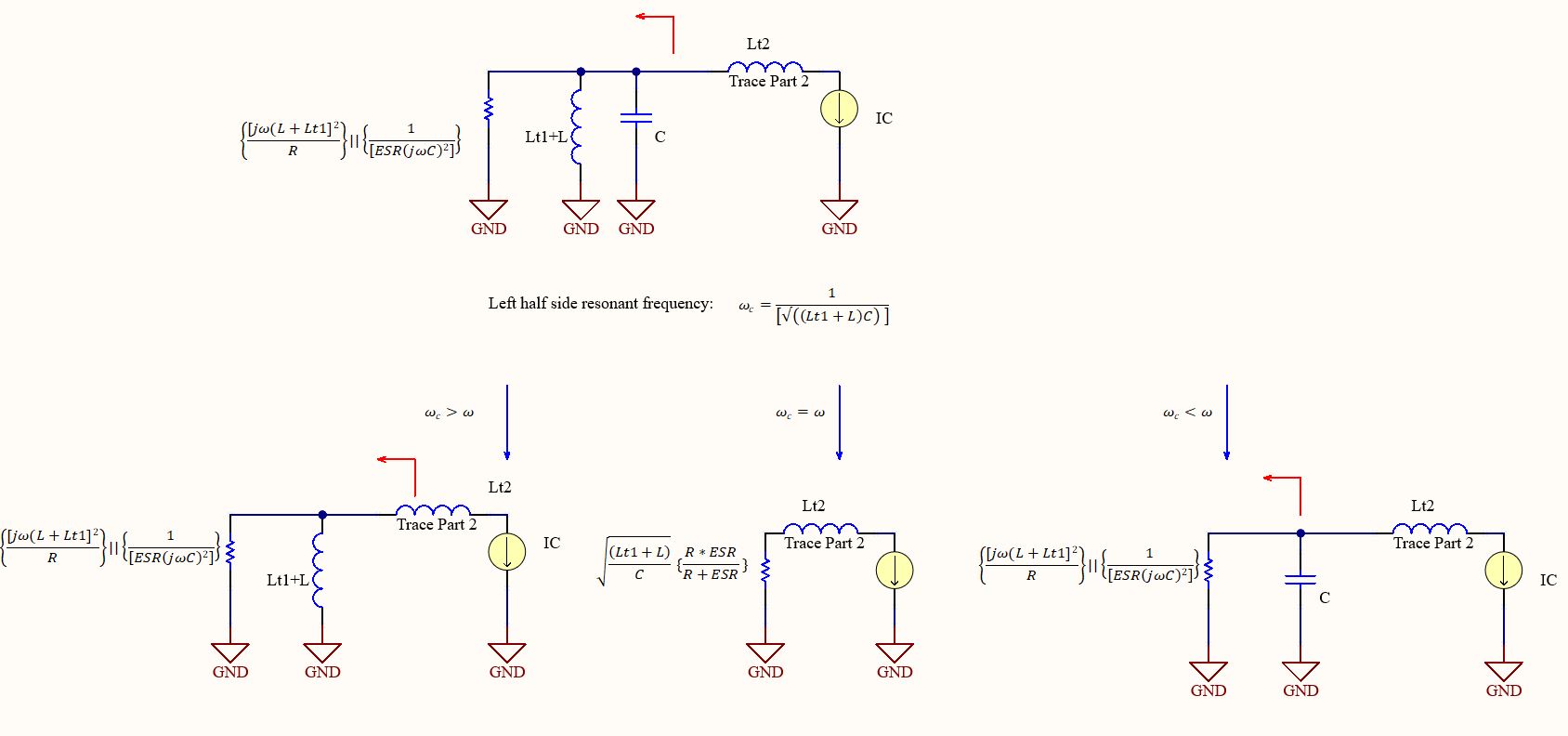 Figure 5. Division into cases.
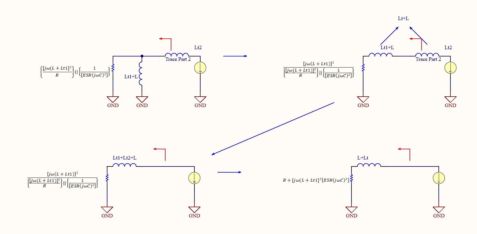 Figure 6. ωc>ω.
 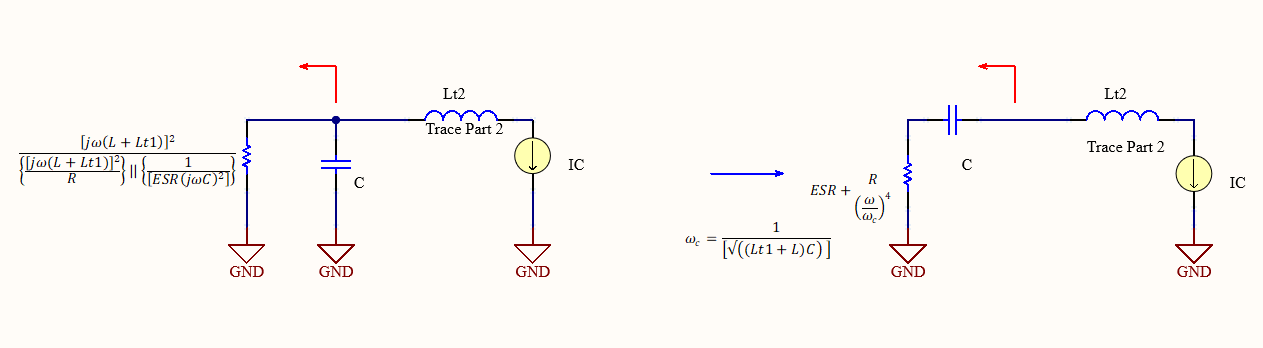 Figure 7. ωc<ω.
 Let us compare each impedance in a table:
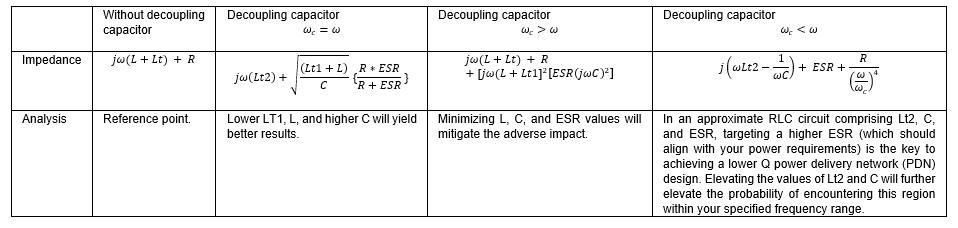
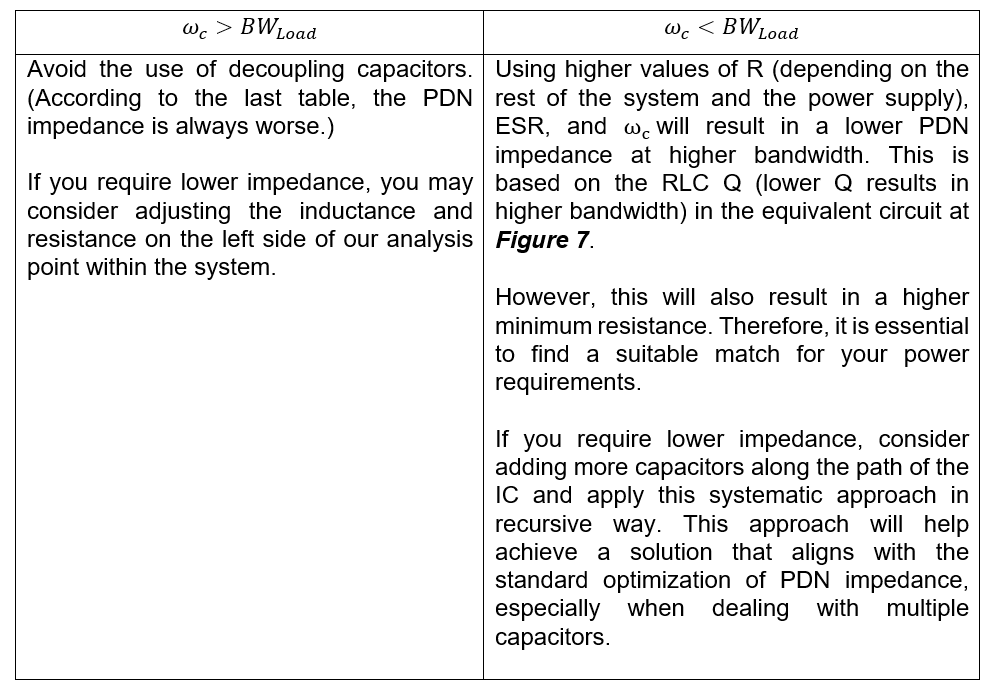
A Systematic Approach for Achieving the Desired PDN Impedance
Note: ωc is approximately proportional to C. In iterative analysis, it is advisable to begin with the promising parameters, such as ESR and your load bandwidth, as the starting point.
In Summary
In summary, the use of decoupling capacitors can potentially lead to negative effects when positioned at a considerable distance from the IC, especially when combined with capacitors of higher capacitance and lower ESR. This configuration can unintentionally create a high Q resonator in your frequency range. Furthermore, a second high Q resonator may form due to the combination of higher inductance along the impedance path up to the point of analysis, prior to the decoupling capacitor, and the line inductance extending from the decoupling capacitor to the impedance at the point of analysis within the circuit. For the second Q resonator, lower ESR or even capacitor removal is more beneficial, especially in the lower frequency range, for your design.
This paper provides a systematic approach for achieving the desired PDN impedance with only one capacitor near the IC and enhancing it with precise simulations can further improve its effectiveness. Furthermore, it has also been observed that relying solely on one type of capacitor at the end may not suffice to meet your PDN impedance goal. In such cases, adding more capacitors along the path can be beneficial, but this may reintroduce the broader challenge of managing impedance in a multi-capacitor PDN.
REFERENCES
- Williams, Tim, The Circuit Designers Companion, 2nd Edition, Newnes, 2005, pp. 190