
Data center and network traffic volumes are increasing exponentially as 5G networks roll out and big data applications are deployed. To meet these demands, physical-layer devices need to support faster transmission speeds, larger data capacities, and assured signal quality. All these factors make accurate and efficient signal integrity analysis more important and difficult for design engineers.
The next-generation 400 GbE standard has been ratified to address these advanced market conditions. It specifies faster speeds using PAM4 to achieve 53 Gbaud. Due to its additional transmission capacity, PAM4 is being widely adopted for 200 GbE/400 GbE implementations. Since the amplitude of each of the three eyes of PAM4 is one-third that of NRZ, the receive circuits require sufficient input sensitivity, as well as forward error correction (FEC) functionality [1].
Test solutions need to deliver improved performance to effectively verify products being designed for the new generation of communications. Bit error rate testers (BERTs) are a key tool for signal integrity engineers to ensure product performance meets industry standards and address PAM4 design considerations. Today’s BERTs must have high sensitivity, generate high-quality waveforms for accurate jitter analysis, as well as other features to effectively test PAM4 devices and systems.
PAM4 Poses Test Challenges
Three eye diagrams are required to conduct accurate analysis on PAM4 devices. That is due to the fact that a PAM 4 signal has four levels. Because noise affects each eye individually, PAM4 signals are at least three times as sensitive to amplitude noise as NRZ.
PAM4 is more susceptible to noise due to reduced eye height. PAM4 requires half of the bandwidth of NRZ for the same data throughput. Eye height at BER is 33% of NRZ at the same supply voltage and it endures lower loss due to half baud rate (see Figure 1). PAM4 individual eye width is 200% of NRZ due to half baud rate. It can be reduced by transitions between non-adjacent levels.

Test Procedures
Each eye diagram for PAM4 can be analyzed implementing the same method as those generated for NRZ. Eye width and height are defined with respect to a BER separately for the lower, middle, and upper eye diagrams. However, the signal-to-noise ratio (SNR) of 4th-order PAM4 is about 10 dB worse than that of the conventional 2nd-order NRZ format. Since SNR of 200 GbE /400 GbE deteriorates with increased transmission speed, it is difficult to achieve the natural error-free transmissions associated with the NRZ format. It is for this reason that FEC transmission methods are necessary.
To ensure device performance, BER and waveform quality evaluations must be done on PAM4 signals. For the most accurate analysis, high-quality waveforms up to 64 Gbaud and high input sensitivity are required.
Jitter Testing Requirements
BER is not the only signal integrity test that needs to be performed to verify device performance is compliant. Other critical measurements include crosstalk and jitter tolerance tests. Error correction tests using jitter-stressed signals are particularly critical in PAM4 signaling, such as 400 GbE.
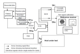
The IEEE802.3 Ethernet standard specifies the procedure to conduct jitter tolerance (JTOL) tests. For example, at the 400 GbE 802.3bs 120E 3.3.2 Host Stressed Input test, as shown in Figure 2, the JTOL test setup specifies impression of random jitter (RJ), bounded uncorrelated jitter (BUJ), and sinusoidal jitter (SJ).
To test the JTOL of a device-under-test (DUT), the BERT needs to apply stresses such as SJ, RJ, and BUJ on the Reed Solomon Forward Error Correction (RS-FEC) pattern. The BERT performs a JTOL test by adding SJ according to the DUT built-in FEC counter value and changing the SJ frequency accordingly.
Performance Requirements
For the most accurate evaluation of actual DUT performance, a high-quality waveform needs to be generated. The waveform quality should have low intrinsic jitter of about 170 fs(rms) and fast Tr/Tf of approximately 8.5 ps to conduct 116 Gbit/s PAM4 error free measurements. This will help obtain high-reproducibility measurements supported by PAM4 signals with open 3-eye waveforms (see Figure 3).

There are additional performance requirements to meet PAM4 verification. The BERT’s pulse pattern generator (PPG) output linearity needs to be controlled so the output level for each eye can be changed. A PAM4 waveform with variable ratio of level mismatch (RLM) needs to be output with good reproducibility for precise analysis, as well.
For error-free BER measurements of 116-Gbit/s (58 Gbaud) PAM4 signals, the PAM4 error detector (ED) in the BERT must have high sensitivity. A BERT with sensitivity performance of 23 mV @26 Gbaud and 36 mV @53 Gbaud produces highly accurate BER measurements, making it easier for engineers to troubleshoot PAM4 devices that would otherwise be difficult to analyze. In addition, true DUT performance can be verified if CEI-112G-VSR-defined worst-case stressed signals can be received at low-error rates of <E-8.
FEC Test Importance
The increased impact of SNR on PAM4 signals demands FEC be conducted, as outlined earlier. FEC allows the maximum uncorrected BER to be increased to 10-6 for electrical signaling. It is even greater for optical transmissions. This allows pre-FEC performance down to BER ~ 10-6 to be measured quickly.
Earlier generations of BERTs allowed errors ranging from E-3 to E-12 to be added to confirm signal behavior. Since this previous error-addition function inserted errors at a fixed interval corresponding to the specified BER, all errors after the signal passed through FEC processing were corrected. To compensate for this scenario, advanced BERTs can now generate virtual patterns of FEC 10-bit symbol units that are separated into 528 or 544 codeword units. A dedicated function inserts correctable and uncorrectable errors by specifying the number of 7 or 15 symbol errors per codeword.
Even when BER results are the same, there are occasions when there are differences in the correctable and uncorrectable results under the FEC environment. To counteract this dynamic caused by error distribution, engineers need to evaluate results after FEC decoding. The error correction degree must be measured based on multilane (typically 4- or 8-lane) FEC patterns defined by each standard. Therefore, high-performance BERTs must generate defined RS-FEC patterns for 400 GbE, 200 GbE, 100 GbE, 50 GbE, and 25 GbE.
There are considerations when measuring multilane FEC transmissions using logical interleaving across all lanes. The reason is that FEC processing is performed on the physical signal, making it difficult to evaluate if FEC correction is possible simply by measuring the BER for each lane. Engineers must transmit the FEC pattern over multiple lanes and then evaluate the FEC decoding results to have a high degree of design confidence.
Conclusion
Deployment of 400-GbE services to meet the demands of 5G and big data has resulted in the implementation of PAM4 into device and system design. Test solutions must be able to conduct accurate 53.125-Gbaud 4- and 8-lane PAM4 BER tests to evaluate 400-Gbit/s and future 800-Gbit/s PAM4 transceivers and devices. A new generation of BERTs is designed to measure high-speed interfaces and supports more accurate BER evaluation of PAM4 interfaces at speeds up to 116 Gbit/s. These tools generate high-speed PAM4 to implement industry-leading high input sensitivity performance.
References
- Liu, Cathy. What is FEC and How Do I Use It? Signal Integrity Journal. https://www.signalintegrityjournal.com/articles/1284-what-is-fec-and-how-do-i-use-it