
High speed digital communication serializer/de-serializer (SerDes) systems are typically modeled in channel simulators to evaluate trade-offs between transmit (Tx) and receive (Rx) circuits and the differential channel connecting them. This channel can be composed of many parts including backplane, printed circuit boards, cable and more. Because of its maturity of development, S-parameters have become the de-facto standard for engineers to describe the frequency behavior of a SerDes system channel. They are measured on actual hardware or simulated in a frequency domain simulator.
This article discusses the issues encountered when using S-parameter files to represent the channel in a SerDes system channel simulator and how to overcome them.
Modeling Serdes Systems in Channel Simulators
SerDes systems are represented in channel simulators with SerDes channels and IBIS-AMI models per the IBIS Open Forum standard (currently at revision 7.1).
Figure 1 shows a typical SerDes system block diagram to be simulated using a channel simulator.
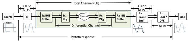
Figure 1. Typical SerDes System Representation in a channel simulator
This block diagram is generic for any channel simulator, but each tool has a specific way to represent this block diagram.
The constituent parts of this SerDes system include the following:
-
TX IBIS-AMI:
-
This model typically contains a Tx equalizer often in the form of a feed-forward equalizer (FFE) with differential IBIS buffer output to the channel.
-
The IBIS buffer can optionally be a 4-port S-parameter file.
-
-
Tx package (Tx Pkg), Channel, Rx package (Rx Pkg):
-
These pieces represent the differential channel.
-
Each part is represented using S-parameter files.
-
-
RX IBIS-AMI:
-
This model typically contains an Rx continuous time equalizer (CTLE), a clock and data recovery unit (CDR) and decision feedback equalizer (DFE) with differential IBIS buffer input from the channel.
-
The IBIS buffer can optionally be a 4-port S-parameter file.
-
A key channel simulator property to keep in mind is that it considers the entire analog content (see the green area in Figure 1; the total channel) between the TX AMI portion and the RX AMI portion is linear and time invariant (LTI). This means that if the Tx or Rx IBIS buffers contain any nonlinearities (as in nonlinear VI tables), those nonlinearities will be linearized and the nonlinearities will not be directly used. As an LTI system, the entire differential analog section in the SerDes system is accurately represented by its signal-ended impulse response. This key concept enables the channel simulator to achieve its fast simulation speeds.
These same fast simulation speeds achieved with channel simulators enable designers to explore a large solution space comprising various model parameters and other system variables. This allows designers to have a much better understanding of how their system will perform under different conditions.
Issues with S-Parameters Used to Characterize the Channel
All channel simulators support a “statistical mode” and a “bit-by-bit” mode. The statistical mode is useful only when the Tx and Rx IBIS-AMI models are linear and time invariant (LTI). However, most SerDes systems have a nonlinearity, CDR, DFE or other type of time variant component in it. Thus, most practical SerDes systems are not LTI and are instead nonlinear and/or time variant (NLTV).
S-Parameters inherently have problems when used in a time domain simulation, including the bit-by-bit mode of the channel simulator.
Though measured on actual hardware, S-parameters deviate from the constraints for physical realizability such as passivity, reciprocity, and causality, or include noise in the measured S-parameters for various reasons. So, to achieve a physically realizable transmission characteristic, the S-parameters must have corrections applied. These corrections must be achieved when converting S-parameters to equivalent impulses in the time domain.
All SerDes system channel simulators convert the frequency domain S-parameter characteristics into time domain impulse characteristics. However, some are less successful than others. In fact, all top six electronic design automation (EDA) channel simulation tools have problems with this. As has been observed by many and especially reported by Romi Mayder of Xilinx Inc. at the 2015 DesignCon conference, the top six EDA channel simulators in the industry give widely varying impulse modeling of S-parameters as well as widely varying channel bit error rate (BER) performance [1]. Though this paper is dated, it still applies today – additional observations have been posted on the web [2][3].
Here is a list of some of the issues with S-parameters as used in a channel simulator:
-
They must start at 0 Hz.
-
If not, then this limitation is overcome by channel simulator tool extrapolating the S-parameters to 0 Hz.
-
-
They must be a linear frequency, sweep from fstart to fstop with a constant step frequency, deltaf.
-
A logarithmic frequency sweep must not be used.
-
Frequency values between two frequency points will be interpolated by the tool.
-
If a log sweep is used, then at the upper frequencies the interpolation of phase will be wrong.
-
-
They must have a step frequency, deltaf, small enough to capture the variation in the S-parameters (excluding noise).
-
Setting deltaf becomes a judgement call by the user based on their perspective on what variations are meaningful.
-
-
They must have a maximum frequency that is high enough.
-
It has been shown [2] that to adequately predict a receiver’s response, the maximum frequency (fstop) of the S-parameters must be at least 60% of the inverse of the receiver’s 20-80 rise time.
-
Example: Given a symbol rate of 6.25 Gbps (1 UI = 160 nsec) and a 20-80 rise time that is 30% of a UI (48 nsec), then fstop should be at least 0.6 * 1/48e-9 = 12.5 GHz. If the rise time is faster, then fstop should be greater.
-
For this example, what if the S-parameters were captured up to 12.5 GHz, but now is to be used for a symbol rate at 12.5 Gbps?
Overcoming a low fstop frequency value will be discussed in a following section.
The total channel, as discussed above, includes the S-parameter frequency domain data and must be converted to an equivalent single ended impulse response that represents the total channel from the Tx IBIS differential output to the Rx IBIS differential input.
It is not a trivial task to produce a causal and passive impulse response from band-limited S-parameters for time domain convolution analysis.
Some channel simulators result in an impulse response that contains a lot of high-frequency aliasing. This distortion can result in misleading SerDes system simulation results.
Overcoming high frequency aliasing in the total channel impulse response will be discussed in a following section.
Overcoming Limited S-Parameter Bandwidth
Consider this example: The S-parameters were captured up to 12.5 GHz, but now are to be used for a symbol rate at 12.5 Gbps.
Using the criteria from the prior section: Given 1 UI at 12.5 Gbps = 80 nsec and 20-80 rise time that is 30% of a UI (24 nsec), then the S-parameter fstop should be at least 0.6 * 1/24e-9 = 25 GHz. If the rise time is faster, then fstop should be greater.
Ideally, the S-parameters should be recaptured up to 25 GHz. Until that is done, it would be nice to use the S-parameters band limited to 12.5 GHz.
Fortunately, a web site offers a solution with a free cloud-based tool. See this web page made available by SerDesDesign.com; free registration is required for use.
For discussion purposes, the S4P file is named Channel_25Gbps_12p5GHz.s4p, with upper frequency 12.5 GHz, and with differential inputs pins, 1 (P side), 3 (N side), and output pins, 2 (P side), 4 (N side).
The web page setup for converting the S4P file is shown in Figure 2.
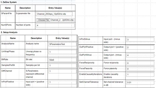
Figure 2. Web page setup for converting the S4P file
Observe that the S4P file Channel_25Gbps_12p5GHz.s4p is uploaded and is defined as having four ports and the input and output pin assignments are made. Observe that the SymbolRate=50e9 and the SamplesPerSymbol=1. The SampleRate = SymbolRate*SamplesPerSymbol and thus the maximum output frequency will be SampleRate/2 = 25 GHz.
After setup, select Run ‘Select to generate causal S-parameters’. The converted S4P file can be downloaded by selecting Download ‘Causal S-parameter file’. To compare the converted S4P file to the original S4P file, select Run ‘Compare Causal S-Parameters to S-Parameters from SParamFile’. Comparison of the S21 and S23 frequency domain responses are shown in Figure 3 with original S4P in red and the converted S4P in blue.
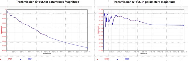
Figure 3. Causal S-Parameters for S21 (left) and S23 (right)
Observe that from 0 Hz to 12.5 GHz, the converted S4P is identical to the original S4P. Beyond 12.5 GHz to 25 GHz, the converted S4P response is smoothly extrapolated. The resultant converted S4P has all corrections applied and its time domain response is causal.
Of course, the extrapolated data is only an approximation to the actual hardware response. Only by measuring the hardware out to 25 GHz will one get the actual hardware characteristic. This approach can keep one’s SerDes system investigation going while one awaits the remeasured S4P data.
Overcoming S-Parameter to Impulse Response Distortions
Whenever using S-parameters in a channel simulator, it is wise to understand the characteristics. Specifically, those of the single ended impulse resulting from the channel simulator conversion of the total channel that includes S-parameter data. If the impulse response has unwanted high frequency aliasing, then it is desirable to overcome these distortions.
As noted earlier, it is not trivial to produce a causal and passive impulse response from band-limited S-parameters for time domain convolution analysis. Some channel simulators result in an impulse response that contains a lot of high-frequency aliasing. This distortion can result in misleading SerDes system simulation results.
For discussion purposes, the following assumes an NRZ 25 Gbps symbol rate and the total channel uses one S4P file with differential input pins 1 (P side), 3 (N side), and output pins 2 (P side), 4 (N side) along with pass-thru Tx IBIS-AMI and Rx IBIS-AMI models that have an IBIS buffer with C_comp = 150 fF capacitance.
Figure 4 shows the S4P data transmission magnitudes for Sij, i < j. The S4P data highest frequency is 40 GHz.
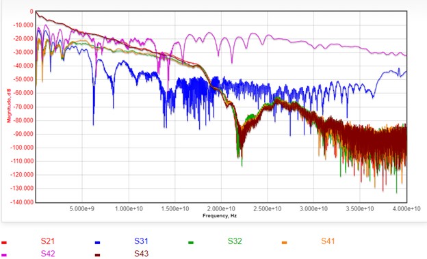
Figure 4. Test channel S4P transmission characteristics Sij, i < j
Observe that at Nyquist (12.5 GHz), the S21 and S43 characteristics have a loss of about 25 dB. Also observe the suck out in the responses at about 22 GHz.
The objective of the channel simulator is to take this total channel characteristic and convert it into an equivalent single ended impulse response. To do this, the differential input and output port terminations are as defined in the Tx/Rx IBIS buffers.
Let hdd21 represent the time domain single ended impulse response derived from the SerDes system total channel. In this time domain derivation, any frequency domain to time domain transformation is not just a simple inverse FFT operation.
As a first example, the SerDesDesign.com free cloud-based channel simulator is used. The SerDesDesign.com frequency domain to time domain transformation inherently does not result in any high frequency aliasing.
When this SerDes system with S4P channel is used in the SerDesDesign.com channel simulator, the resultant impulse response is shown in Figure 5.

Figure 5. Test channel SerDesDesign.com time (left) and frequency (right) domain impulse response
Observe that this channel time domain impulse is clean and smooth with no ringing. The frequency domain view shows smooth extrapolation beyond the S-parameter upper frequency of 40 GHz. In the frequency domain view, observe that the hdd21 response (blue) matches the sdd21 response (red) up to 40 GHz, with reduction of the noise inherent in the S-parameters as the frequency approaches 40 GHz.
As a second example, when this SerDes system with S4P channel is used in the Keysight automatic debiting system (ADS) channel simulator, the resultant impulse response is shown in Figure 6 (time domain, left; frequency domain, right).
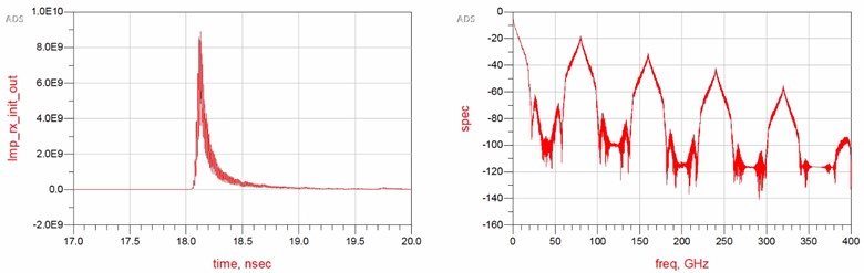
Figure 6. Test channel ADS time (left) and frequency (right) domain impulse response
In this ADS test, the ADS channel simulator exported to its dataset the input and output impulse response at the Tx and Rx IBIS-AMI models AMI_Init() function. The impulse response used was the one exported by ADS at the Rx IBIS-AMI model AMI_Init() output. The simulation time step is set by the channel simulator to 1/SymbolRate/SamplesPerSymbol = 1/SampleRate = 1.25e-12 sec. The ADS data display equation fs() function was used to convert the impulse response from its frequency domain response to 400 GHz. This frequency domain upper frequency of 400 GHz is set by the channel simulator to one half the sample rate. Every channel simulator that uses a 25 Gbps SymbolRate and 32 SamplesPerBit will have this sample rate, time step, and frequency domain upper frequency.
Observe that this ADS channel time domain impulse has a lot of ringing in it. This high frequency aliasing is better observed in the frequency domain. Observe the high frequency aliasing beyond the S4P upper frequency of 40 GHz with aliasing peaks at 80 GHz, 160 GHz and beyond. The ADS impulse conversion process results in accurate frequency domain characteristics to the S-parameter maximum frequency, 40 GHz in this case, but also results in high frequency aliasing beyond this S-parameter maximum frequency.
Ideally, the S-parameter based channel does not result in high frequency aliasing in the impulse response. In the above ADS example, the high frequency aliasing may be undesirable. When that is the case, what can be done to remove the aliasing?
One approach is to enable the ADS ChannelSim anti-aliasing filter. Set ‘Anti-aliasing window size in time point’ in the ChannelSim > Convolution > Advanced… tab. Set Fc to the desired half width of the filter main lobe; set to 40 GHz in this example. Set M = 2*SamplesPerSymbol*SymbolRate/Fc = 40. See the resultant ADS impulse response time and frequency domain response in Figure 7.

Figure 7. Test channel with ADS anti-aliasing time (left) and frequency (right) domain impulse response
Observe that this ADS channel time domain impulse has no more ringing in it. The frequency domain response shows significant attenuation of the high frequency aliasing. Unfortunately, this is at the cost of additional roll off at Nyquist (12.5 GHz); 3 dB in this example. Also, the original S-parameter data frequency domain suck out at 22 GHz as shown in Figure 4 is distorted and not visible.
Another approach is to convert the S-parameter data into ‘Causal S-parameters’ as was discussed in the prior section using the free cloud based tool made available by SerDesDesign.com.
In this case, referencing Figure 2, upload the SParamFile, set SymbolRate to the desired sample rate (25 Gbps in this case) and SamplesPerSymbol (32 in this case), and run the tool as was described in the prior section.
One can then download the converted S4P file and use this file in ADS. The resultant ADS channel impulse response will not have any high-frequency aliasing and will appear as SerDesDesign.com response shown in Figure 5 above. The ADS channel simulator resultant impulse response is shown in Figure 8.

Figure 8. Test channel with ADS anti-aliasing time (left) and frequency (right) domain impulse response
Observe that this ADS channel time domain impulse has no more ringing in it. Also, there is no more high frequency aliasing in the frequency domain response with no additional loss to the original data to 40 GHz. Even the original S-parameter data frequency domain suck out at 22 GHz is preserved.
Conclusion
Because of their maturity of development, S-parameters have become the de-facto standard for engineers to describe the frequency behavior of a SerDes system channel. Though, even the most popular channel simulators in the market have limitations when converting S-parameters to their equivalent time domain impulse representation.
This article has reviewed various issues with S-parameters. It addressed workarounds used to overcome specific issues when S-parameters are band-limited to an upper frequency that is lower than desired for good rise-time resolution or when conversion to impulse responses result in undesirable high frequency aliasing in the impulse response.
As part of the S-parameters issues discussed in this article, reference was made of the free web/cloud-based tools that include channel simulator and S-parameter correction tools. The channel simulator includes features for a fee that include behavioral modeling SerDes Tx/Rx designs and features for a fee for converting Tx/Rx designs into IBIS-AMI models.
By using S-parameters in channel simulators and paying close attention to the quality of the S-parameters, one can have confidence in the derived SerDes design eye diagrams and other analysis methods.
References