Yes, you read that right. Unheard of? Read on.
The history of electronics is checkered with many things that should have caught on, and others – like the internet – that surprised us with their ubiquity. This article is about something I expected to become one of the greatest boons for Signal Integrity (SI): SerDes Equalization Settings (SES, only accessible through software). I was wrong.
You’d be surprised to learn how many of my customers’ SI issues – particularly those in the field – I’ve fixed in software. Crosstalk issues even; can you believe it? Yet to me, even more surprising has been the overwhelming majority who are uninterested in optimizing and programming the settings. You see, after 30+ years of solving SI issues in hardware (e.g., terminations, 3D solvers, controlled impedance, length matching, etc.), sheer momentum has prohibited us from recognizing a gift horse when it came along. You adapt the hardware to the I/O and not the other way around, right?
Because the SES wound up as bits in firmware their power is rarely exploited. There have been those who bravely tried to adjust the SES, yet were unable to navigate their company’s hardware/software organizational divide to get a couple bits flipped in the bowels of a mysterious register – the power of which was understood only by the SI engineer. If the SES were hardware pin strappings accessible to the schematic team no doubt they’d be used more often.
So why are all those SES there? Thousands of combinations of them, even? They are the fodder of brilliant SerDes designers who set out to make a single IO that could handle a variety of system implementations and serial standards. Oddly enough, making the SerDes enormously adaptable was substantially simpler than understanding the system requirements. And then there’s the FPGA SerDes Transceiver that must handle any and every system scenario anyway.
In my observation, success in using the SES has been limited to very small or very large companies; the former because the same engineer manages both the PCB and the firmware, and the latter because achieving 150% more design margin in their high-volume products is relevant amidst a myriad of manufacturing tolerances ([1] slides 27-36). Perhaps you will be among those who succeed as well. My hope is to motivate you to do so.
What’s More Important, Hardware, or Software?
You don’t have to work in electronics very long to wind up in that debate. In this section, I’ll ask that question as it relates to serial links. You might be surprised by the answer.
Part of why my company specializes in serial links is because I have found them to be robust, extensible, and even elegant technology – particularly when compared with their messier cousin, DDR. I have found the hardware/software aspects of the technology to be quite interesting and have felt for a while now that – while there are a few important things to know and do in hardware – the dominant factor affecting performance is the software, or the SES. To illustrate my point, I constructed a simple serial link using modern PCB materials (Dk=3.4, Df=0.008). When driving the link at 8 Gbps with one default-ish post-cursor of Tx equalization (30%) and no Rx EQ, eye performance is essentially flat as the link grows from 2” to 20” (see Figure 1, red=height, blue=width). What?! That’s a 10x variation in the hardware’s trace length. After years of trying to shorten and/or match traces to 5 mils, here’s technology that doesn’t seem to care much about length.
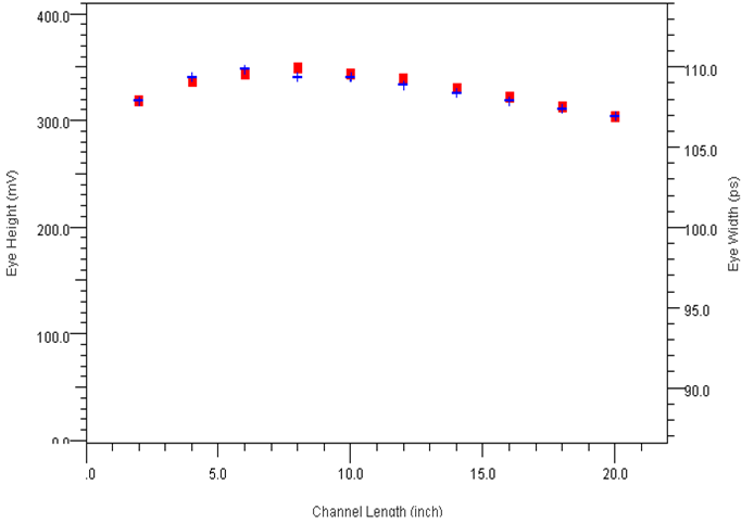
Figure 1. Eye Height/Width vs. Channel Length, Hardware Flexibility (all plots created in MATLAB’s Signal Integrity Toolbox™)
While Figure 1 suggests the layout team can miss by an order of magnitude, Figure 2 shows that the software team must be much more careful. Suppose there’s a firmware update in which the software team flips a bit or two and incorrectly applies the default Tx “post-” cursor EQ to the “pre-” cursor, perhaps misreading a spec intended for the “+1” tap and gives it to the “-1” tap. After all, what do “taps” have to do with a software stack anyway? In this scenario, Figure 2 shows a 3x decrease in eye performance (red=height, blue=width) throughout the same channel length variation of Figure 1.
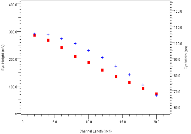
Figure 2. Eye Height/Width vs. Channel Length, Software Inflexibility
So, let’s see, a 7% performance variation against a 10x change in hardware (Figure 1), versus a 300% performance variation due to a couple register bits in software (Figure 2). How could that be? Is this really a fair comparison? You can decide, but after working with these technologies for a couple decades I believe it is. Either way, if I’ve spurred you to manage both the hardware and software aspects of link performance, we both win.
Using Software to Improve Performance
The examples above illustrate the power hiding in the SES – power you can unleash to substantially improve or fix your design. In this section, instead of thinking about what can go wrong when adapting the SES let’s have a look at what can go right.
Freezing the channel in the above examples at a length of 4”, the first eye in Figure 3 (left) reveals the channel is significantly over-equalized with the default SES. This is generally the case in many shipping systems, as IC companies have found over-equalization to offer acceptable – albeit non-optimal – performance that is impervious to hardware implementation variation, as shown in Figure 1. The unfortunate side effect is over-driven (noise=crosstalk) signals that sacrifice performance and power. This is illustrated in Figure 3, as turning off the SES either doubles eye margin (center) or cuts power in half with 20% better eye margin (right) when reducing Tx voltage amplitude to 50%.
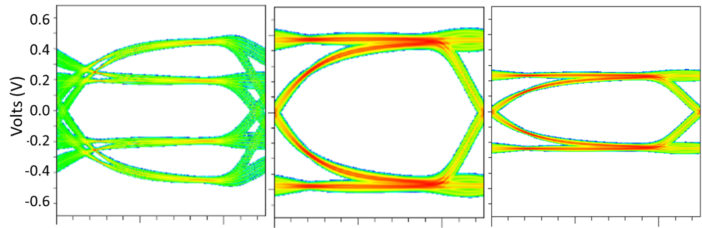
Figure 3. Using Software to Achieve 2x Eye Margin or Power Reduction
As the improvements shown in Figure 3 can be achieved in most systems, why is this not happening? True to the history of SI, many hardware teams need to get stung before applying repellent, while others simply do not realize how much SI performance optimization is hiding inside the chip (SES=Software). For this reason, we documented how adapting the SES can achieve performance gains up to 200% across a wide variety of channels ([2] slides 11-18) or 3x-5x improvements when using PAM4 ([2] slide 19). Learn how to optimize the SES through understanding which types of EQ to apply when, using techniques described in this paper ([3] pages 15-18). Test your design scenarios using a trial version of the software used in both papers ([2],[3]).
In Conclusion
It’s important for hardware and SI engineers to understand how to optimize SES to both fix problems and improve system performance. While some standards and systems aspire to automagically optimize the SES using software routines at boot-up, experience suggests human beings are more successful. Without question, your simulator or COM analysis setup provides a way to explore SES options – normally through IBIS-AMI models and their configuration settings. Why not give it a try? It’s simpler than you think.
Have you used SES to rescue or improve your design? If so, share your SES story in the Comments section below.
This article is an excerpt from Donald Telian’s new book “Signal Integrity, In Practice,” a practical handbook for Hardware, SI, FPGA, and Layout Engineers.
References:
[1] DesignCon AMI Panel: “Getting the Most from IBIS-AMI: Tips & Secrets from the Experts”
[2] A SerDes Balancing Act: Co-Optimizing Tx and Rx Equalization Settings to Maximize Margin
[3] DesignCon Paper: “New SI Techniques for Large System Performance Tuning”
Related Resources
- Which Discontinuities are Small Enough to Ignore?
- Book Review: Signal Integrity in Practice by Don Telian
- Donald Telian Publishes Book: “Signal Integrity, In Practice”