
Ask any engineer how to reduce the cross talk between two signal traces and the most common answer will be to add a guard trace. This should be the last resort, not the first choice. Guard traces can often introduce more problems than they solve. Find out why we say this in this article.
Below we have written a summary of our main points, and all of the rest of the details can be found in our vintage DesignCon paper (and Best Paper Award Winner), ”Dramatic Noise Reduction using Guard Traces with Optimized Shorting Vias,” by Eric Bogatin and Bert Simonovich, DesignCon 2013.
Motivation to Use a Guard Trace
A guard trace is a signal trace inserted between two signal lines with some type of connections on the ends. Its intended purpose is to reduce the cross talk between the two traces. To distinguish the two traces, we call one trace the aggressor and the other the victim.
When we launch a signal on the aggressor, there is a different signature of the noise on the victim line at the near end or the far end of the line. To distinguish these two ends, we refer to the noise as at the near end, or propagating in the backward direction or at the far end or propagating in the forward direction.
How much cross talk is too much? Of course, “…it depends.” If the allocated noise margin of acceptable cross talk is 5%, and it comes from aggressors on either side of the victim line, then the maximum allowable noise would be 2.5%.
The behavior of a guard trace is different in a microstrip or a stripline topology. They must be analyzed separately.
In microstrip, a pair of 50 Ohm lines, with an edge to edge spacing equal to their line width, will have a saturated near end cross talk coefficient (NEXT) of about 3.8%. This means a 1 V rising edge on the aggressor will generate a 38 mV backward propagating noise signal on the victim line. Of course, once this noise is generated on the victim it is subject to reflections based on the terminations at the ends just as a signal would be.
An actual NEXT of 3.8% means if there were two aggressors, one on either side of the victim, the worst case NEXT could be as high as 7.6%, exceeding the limit. Does this mean we should use a guard trace?
In order to add a guard trace between the two signal traces, you have to move the traces apart. The minimum spacing is 3x the line width. This would allow a guard trace of the width of the signal trace, with a clearance of 1x the line width on either side.
Just moving the traces far enough apart to fit a guard trace reduces the NEXT from 3.8% to 0.8%, far below the limit value of 2.5%. If 0.8% is an acceptable noise level, there is no need for a guard trace.
However, there are some very low noise applications where the acceptable noise coupling must be less than -60 dB. This is 0.1%. In this case, adding a guard trace in microstrip topologies does virtually nothing.
Analysis of guard traces by simulation
Using Keysight’s ADS with a built in 2D boundary element field solver, the impact of a guard trace on the coupling between an aggressor and victim line can be analyzed. The field solver takes into account the reduced field coupling due to the spacing, the impact of the guard trace metal on the field distribution and the impact of the noise coupled onto the guard trace and re-infecting the victim line.
The simulated noise on the victim line, using the three different termination options on the guard trace: open ends, shorted ends and terminated ends, was analyzed and is shown in Figure 1.

In microstrip, there is no advantage in using a guard trace, and with a termination other than 50 Ohms on the guard trace, the victim noise is actually worse with the guard trace.
The same analysis can be done for stripline. The near end cross talk without a guard trace and tightly spaced in stripline is 5%. This is a lot. But again, just pulling the traces far enough apart to fit the guard trace, reduces the coupling on the victim line to 0.3%, below any typical digital cross talk spec.
When the guard trace is added, its impact is different for the near or far end noise. Figure 2 shows the simulated behaviors with three different terminations on the guard trace in stripline.
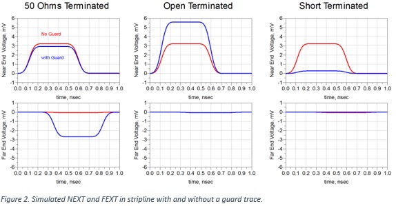
In stripline, there is a dramatic reduction in the NEXT with no additional hit to far end cross talk, using a guard trace with its ends shorted to the return paths. This is recommended condition.
However, the NEXT is already as low as 0.3% with no guard trace. And if the guard trace were kept open at the ends, it would actually increase the cross talk on the victim trace.
Conclusion
In all digital applications, a typical acceptable level of near end cross talk is on the order of 2.5%. A NEXT below 1% can be achieved by just increasing the spacing between the victim and aggressor and not adding a guard trace.
In microstrip if a guard trace is added and left open or shorted at the ends, the cross talk with the guard trace is higher than if the guard trace was left out.
In stripline a guard trace shorted at the ends will reduce the cross talk from 0.3% to less than 0.02%. But, if the guard trace is left open or terminated with 50 Ohms, the NEXT and FEXT will be higher with the guard trace than without.
If you need less than 1% cross talk, consider using stripline. If you need less than 0.3%, use as large a spacing between the aggressor and victim line as practical. Use a 2D field solver to determine how much cross talk you have without a guard trace.
The risk of using a guard trace is that if it is not implemented exactly the right way, the resulting noise on the victim line can often be higher than if the guard trace is not added. Given the potential danger of miscommunication between the hardware designer and the layout engineer, there is a high risk a guard trace will not be implemented correctly. And never, ever, use a guard trace without first doing your own analysis. Just throwing metal at the problem may make it worse, not better.
Read the full story in the complete paper originally presented at DesignCon 2013.