.webp?t=1675141833)
Simply put: We need more bandwidth. In this era of extreme data collection and processing, we’re now designing systems using SERDES at 112 Gbps PAM4 (28 GHz Nyquist rate) per lane and looking at 224 Gbps and beyond. One of the key challenges in implementing these high data rates is choosing the interconnect that will maintain appropriate signal integrity, preferably with some margin. In this article, we’ll go over some interconnect design choices in the context of the new PCI Express® (PCIe®) 6.0 specification and provide suggestions on how to overcome design tradeoffs and challenges.
Finding a Standard
In the high-tech industry, the Peripheral Component Interconnect Special Interest Group (PCI-SIG®) was founded in 1992. For more than 30 years, PCI-SIG member companies have championed PCI® and PCIe technology as the de facto interconnect in any number of high-performance computing applications.
The sixth generation of PCIe technology, fully released in January 2022, again doubles the bandwidth (64 GT/s) compared to the previous generation. Additionally, PCIe 6.0 offers processor-agnostic, cost-effective, power-efficient, low-latency, scalable connectivity between components while maintaining backward compatibility. These key features help PCIe 6.0 support the insatiable bandwidth demand in artificial intelligence, machine learning, networking, communication systems, storage, crypto mining, high-performance computing applications, and more. In addition, it is driving the need for innovative interconnect systems to handle the increased data rates.
New Spec: New Challenges
Doubling the data rate for PCIe 6.0 presents challenges for two-level signaling, where a suggested 32 GHz operating frequency and associated insertion loss and noise reductions put an extreme burden and expense on PCB design and manufacturing. For the last few decades, high-speed links in the data center and compute environment have used two voltage levels: low voltage representing binary 0 and high for 1 (non-return to Zero (NRZ) or PAM2). As frequency increased to achieve more bandwidth, loss, and reflection became a challenge. The solution, four-level pulse amplitude modulation (PAM4), enables PCIe 6.0 to double the data without increasing the operating frequency.
Operating at a decreased signal amplitude for each bit (1/3rd), the PAM4 link experiences a 9.54 dB reduction in signal-to-noise ratio. To achieve the reduction in noise, some improvements were necessary. For example, PCIe 6.0 includes advances in receiver equalization to compensate for frequency-dependent loss, with an increase in decision feedback equalization (DFE) from 3-taps to 16-taps. In addition, loss budget requirements were reduced for larger root complex packages, and the channel target was reduced from 36 to 32 dB.
Next Generation Connectors
Similarly, we expect loss and noise requirements for PCIe 6.0 CEM connectors to tighten. Although the 6.0 CEM specification is not yet released, we can expect new metrics like integrated crosstalk noise (ICN) to maintain an important presence in PCIe 6.0 CEM specification. ICN is a weighted, single-number metric used to test the overall connector crosstalk for compliance.
To perform this test, a weighting function (shown on left in Figure 1) is defined that is proportional to the power transferred through a PCIe 32 GT/s NRZ or 64 GT/s PAM4 system and is then used to filter the measured connector crosstalk power sum. (Resonances and other minor excursions beyond the limit line that have little relevance to actual system bit-error-rates will be permitted.)
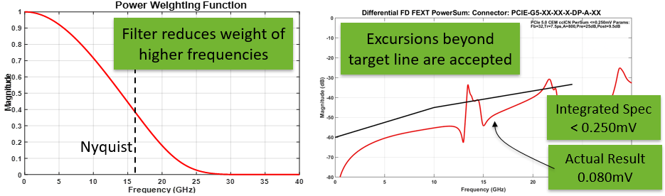
Figure 1. ICN is a weighted, single-number metric that is determined (left) to filter the measured connector crosstalk power sum (right), and thus test the overall connector crosstalk compliance.
As the insertion loss target has been reduced in the PCIe 6.0 specification, there is also a need to improve PCB material to meet sufficient channel reach, targeting near or below 1.0 dB/in at 16 GHz.
Cable Solutions Rise to the Challenge
To satisfy the more stringent loss targets in the PCIe 6.0 specification, designers can consider a shift from PCB transmission line to cabled solutions. In addition to improving loss performance, this approach can also extend reach. For instance, in Figure 1, the Samtec PECFF Emulation Platform illustrates configurable cable topologies between mock GPU cards on a SFF-TA-1002 based backplane in a typical artificial intelligence (AI)/machine learning (ML) system architecture. In this case, the trade-off ratio is 10:55 in. (PCB:Cable) using 34 AWG Eye Speed® Twinax in the chassis.

Figure 2. Samtec’s PECFF Emulation Platform showing configurable cabled topologies between mock GPU cards in a typical AI/ML system architecture.
Loss Budgets
System architecture decisions (PCB and cable length, whether a repeater is needed, etc.) can be made without extensive simulation expertise by using a loss budget with appropriate estimates. However, raw arithmetic assumptions of system losses do not consider the complexity of increased noise sensitivity of the PAM4 link, so they can lead to optimistic and potentially disastrous assumptions. To achieve reliable conclusions, it is wise to include a noise penalty determined from rigorous simulations.
Table 1 offers an example of PCIe 5.0 and 6.0 design by loss budget. Included for each is a 4.0 dB penalty budget item for un-simulated noise effects, informed through rigorous simulations results from PCI-SIG work group members. The first two entries represent 1-connector PCB designs for PCIe 5.0 and 6.0. The last column compares the extended reach possible with 7 dB cable assembly budget, achieving 1-meter cable with 3” host and 4” card PCB lengths.
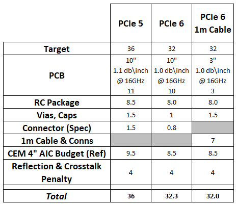
Table 1. A sample PCIe 5.0 and 6.0 design by loss budget with 4-dB built in penalty budget, comparing a 10” PCIe 5.0 and 6.0 PCB approach to a 1m PCIe 6.0 cable assembly.
Ways Forward
Satisfying the signal integrity requirements of a receiver is getting significantly harder to achieve. As we continue to push up the Nyquist rate, the loss per inch of the PCB rises significantly. Mid-range PCB dielectrics can have a loss as high as 1.4 dB/in at 16GHz, and breakout region designs around the package and connectors can be around 2dB each. This can very quickly eat away the loss budget and significantly minimize component placement flexibility. In addition, crosstalk becomes a greater risk as smaller geometries become antennas at these frequencies, which often leads to more PCB layers to achieve good isolation.
One way to mitigate these challenges is by using a Flyover® cable (see Figure 3a) near the transceiver, getting the signal off the PCB as soon as possible. Samtec’s Flyover cables, for example, are fully shielded differential pairs, so crosstalk is minimized within the assembly. They use high-end uniform dielectrics and a much larger conductor than any high-speed PCB trace, which minimize losses to around 0.15-0.20 dB/in at 16 GHz, depending on the gage used (or 0.18-0.26 dB/inch at 28 GHz, see Figure 3b). This allows for much more reach in the system and, therefore, enables placement flexibility.
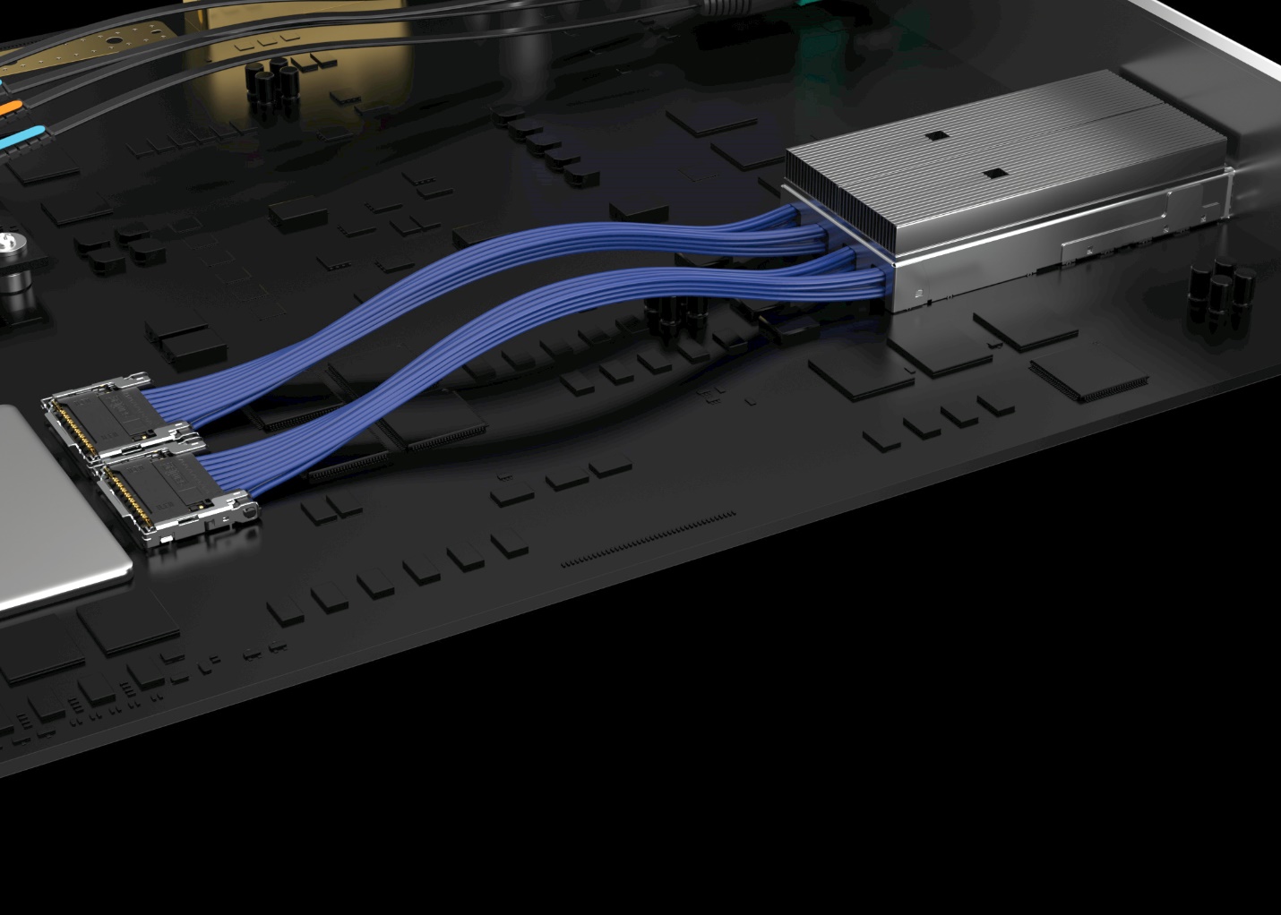
Figure 3a. Image of Samtec’s Double Density Flyover QSFP cable system connecting to Si-Fly® interconnect.
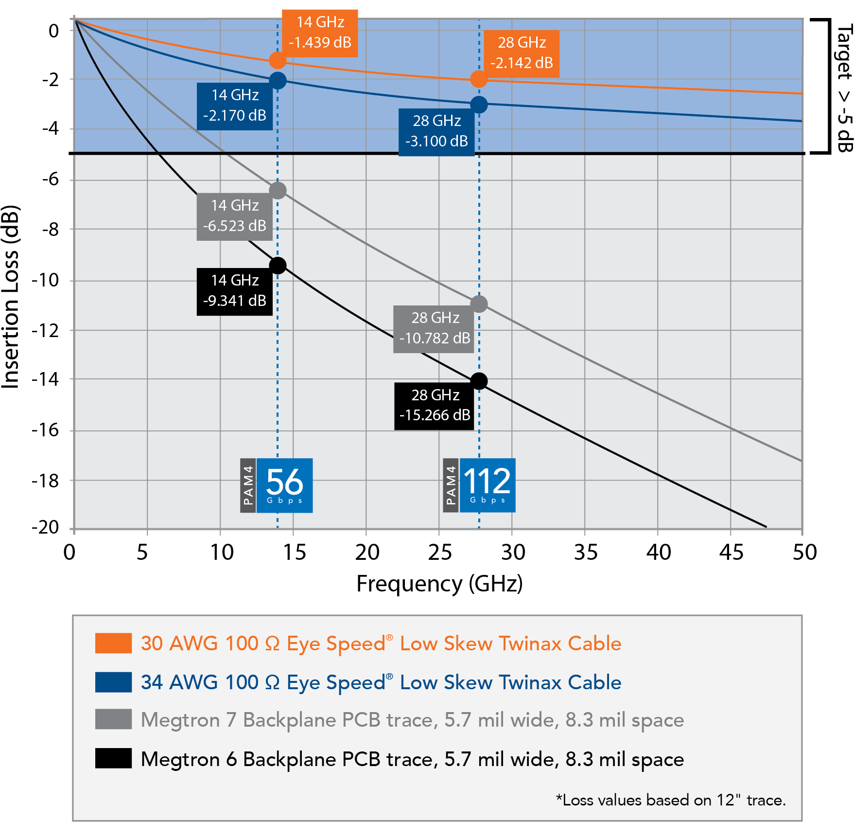
Figure 3b. PCB trace vs. Flyover loss, showing 7x cable reach over Megtron 6
Without a doubt, the PCIe 6.0 specification is enabling extremely high data rates. Although the standard is backward compatible with PCIe 5.0, designs will have to change dramatically to manage the loss and latency issues of the new specification. Although some test and measurement issues may remain, the good news is that interconnect design methodologies and products already exist to get the most out of the latest PCIe 6.0 designs.