
Oscilloscopes and bit-error-rate testers (BERTs) are high-speed test instruments that can characterize PCI Express 4.0 16 gigabit per second (Gbps) serial data signals. While real time oscilloscopes capture blocks of contiguous data with high resolution and the ability to analyze waveform shape, BERTs stream the edges in actual time with 1-bit vertical resolution, offering both advantages and disadvantages to both classes of instruments. By combining the capabilities of these two instruments, a powerful combination of actual-time error detection and characterization can emerge.
Connectivity
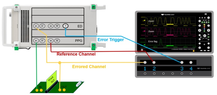
The PCI Express 4.0 standard specification requires an oscilloscope with at least a 25 GHz analog bandwidth, and a BERT that can test bit rates of at least 16 Gbps. The BERT provides a known input pattern to the PCI Express device under test (DUT) and the DUT is instructed to regenerate the identical bit pattern while placed in loopback mode. Since a BERT can output an error trigger output when a bit error is detected, this signal can be routed to the oscilloscope as an input to coordinate a synchronized capture when an error occurs.
Shown in Figure 1, a known pattern is connected from the BERT PPG D1 output to the PCI Express DUT input via a 2.92mm K-type cable. The DUT attempts to regenerate the same data pattern, while the DUT output is routed to both the BERT error detector input and the oscilloscope channel 1 via 2.92mm K-type tables and a power splitter. An error-free reference signal is connected between the BERT D2 output to the oscilloscope channel 2, along with the error trigger signal from the error detector output to the oscilloscope channel 3.
Error Detection Method
In order to determine the jitter tolerance of a PCI Express device, controlled quantities of random and sinusoidal jitter are injected into the signal by the BERT. At some point, the PCI Express 4.0 device under test will likely fail to repeat the same pattern applied to its output, resulting in a bit error.
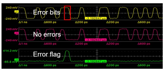
Shown in Figure 2, the oscilloscope triggers on the error detector output and captures all three waveforms. The PCI express waveform with potentially errored bits (yellow) and the PCI Express reference waveform with no errors (pink) are subtracted to create an error flag waveform (green). Since the green waveform is the difference between the potentially errored waveform (yellow) and the error-free reference waveform (pink), when the device is running error-free the green waveform will ideally display a flat line indicating that no errors have occurred.
However, when a bit error occurs, the difference between the two waveforms will produce an error flag, since one waveform is in a high state while the other is in a low state during that bit period. The error flag shown in Figure 2 is due to the yellow waveform showing a logic 1 while the reference waveform shows a logic 0 at the same time position. The errored bit is highlighted in red.
The error flag points to the precise location in time where the bit error has occurred. With the error location in time precisely identified, and the oscilloscope's ability to capture other waveforms, the source of the error can be correlated with other signals for root cause-and-effect analysis. By combining the BERT's ability to stream data in actual time, combined with the oscilloscope's ability to capture and display the waveform shape details when the event occurs, the exact error location can be identified and viewed, allowing for advanced debug capabilities far beyond what either instrument can provide independently.