Samtec Signal Integrity Engineer Steve Krooswyk recently presented “PCI Express: Is 85 Ohms Really Needed?” as part of the gEEk® spEEk webinars. Here is a summary of his key points.
High-speed systems today face many simultaneous impedance requirements that must be achieved in the same stack-up: differential impedances at 100 ohms for ethernet, USB at 90 ohms, PCIe at 85 ohms, and a myriad of single-ended DDR requirements. We want to follow the specification, selecting components and routing traces at the correct impedance. However, sometimes there are hurdles, such as the preferred component is not available in 85 ohms, or the upstream package is yet another impedance. We want to follow this mantra of 85 ohms for PCIe, but it may not be so easy. What can we do, and what does the specification say?
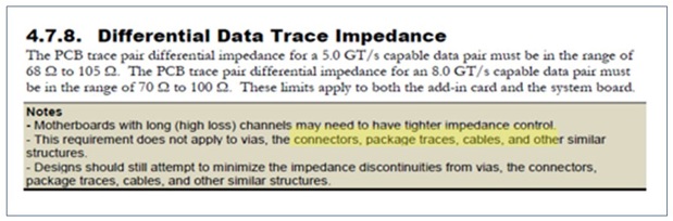
Let’s go directly to the specification. About the PCIe 85 ohm requirement, the specification says “This requirement does not apply to vias, connectors, packages, cables, and other similar structures” PCI Express Card EletroMechanical Specification Revision 4.0 version 1.0, section 4.7.8.
Connectors outside of 85 ohms are acceptable, and in fact this is common. For short durations, the contacts are exposed to air (like CPU sockets), which raises the impedance. These short excursions will be higher than 85 ohm, but play no detrimental role in the return loss. In fact, it is quite common to observe 110 ohms on compliant Gen3 and Gen4 connectors.
PCB routing is required to be 85 ohms for the case of interoperable systems and cards that follow the CEM (Card EletroMechanical) specification – ensuring a matched impedance for any mated device.
All other systems — with any number of connectors or cables — may use any PCB impedance. Many packages and connectors are designed to support multiple I/O and will have an impedance of 100 ohms, or even 93 ohms as a balanced compromise. I recommend to review and determine what impedance may be optimal for your specific design.
It is becoming more common to see 93 ohm routing, but it is not unreasonable to continue with 85 ohm routing alongside higher impedance packages and connectors. Lower PCB impedance does tend to have some advantages including lower losses, better matching to dense BGAs, and more tolerance to impedance variation to name a few.
Cable Impedance
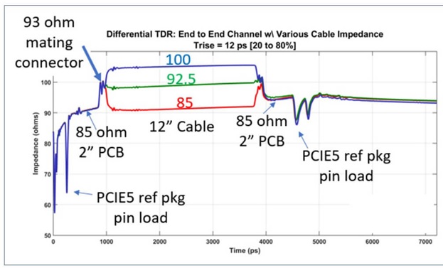
It is tempting to select cable impedance to match what is used on the PCB. However, there are a couple of anecdotal considerations. First, higher frequency reflections are a greater function of the mating connector impedance than the PCB itself. If an incoming signal experiences an increase from 85 on PCB up to 93 ohms for a given connector, it is best to remain at 93 ohm and not create new reflections by following it with a decrease to 85 ohm cable.
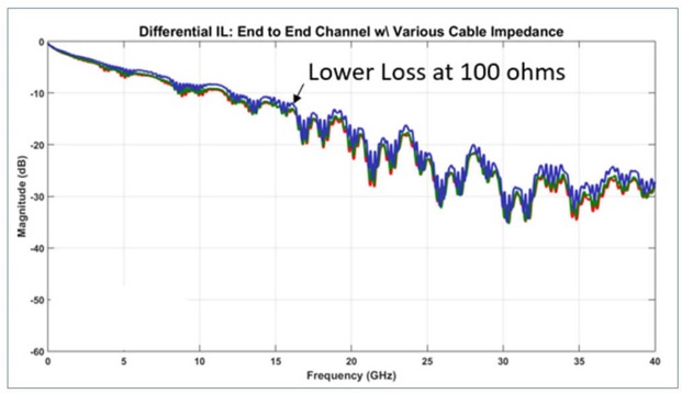
Secondly, the relationship between impedance and loss is inverse of the PCB relationship. That is, higher impedance cable has less insertion loss whereas higher impedance PCB would otherwise be more loss. The loss difference between 85 and 100 ohms is as much as 14 percent, and is explained in the actual geometry of the twinax. This is the experience for Samtec twinax eyespeed cable and may not be the experience for all cable suppliers.
Ultimately, cable impedance choice depends on the priorities for your system. If insertion loss is the greatest constraint, then 93 or 100 ohm cable is the best choice.
Hopefully you will be able to review the specific design, select the optimal impedance, and not be constrained to 85 ohms. Remember, the specification only requires 85 ohms for the PCB routing when using the interoperable CEM slot. When it comes to connectors, cables, packages, and PCB routing to other connectors, the specification permits any impedance that is optimal for your design.
Editor’s Note: Here’s a link to Steve’s webinar, which contains much more detail and discussion: “PCI Express: Is 85 Ohms Really Needed?"
The contents of this post originally appeared on the Samtec blog.