
Switch-mode power supplies (SMPS) are commonly used DC-to-DC converters in many electronic components. By their nature, they can generate a lot of radiated emissions. Unless care is taken, it is difficult to separate what is the actual voltage on the power rail and what is an artifact due to the way we probe the circuit. A recent student design project illustrates the importance of using best measurement practices to avoid EMI pick up and cable reflection noise.
In this project, a Texas Instruments TPS565201 SMPS controller was implemented in a simple 2-layer board. This voltage regulator module (VRM), is a step-down DC-to-DC converter, implemented as a buck regulator.
This means a control module generates a pulse width modulated (PWM) waveform to control the switching of two MOSFET switches, one on the high side and one on the low side. These gates basically switch the input supply voltage into the output, a stepped-down voltage, generating an output pulse train at the voltage of the input. This circuit is shown in Figure 1.
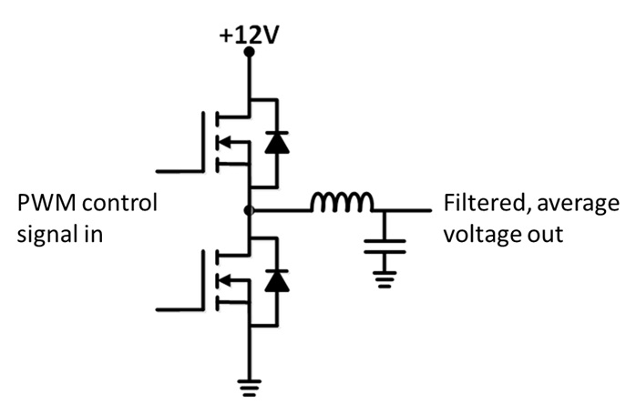
Figure 1. Simplified buck converter circuit showing the PWM control signals and high and low MOSFETS switching into a lower pass filter.
A simple 2-pole LC low pass filter is used to filter this higher voltage pulse train into its average value. The output voltage of the buck regulator is basically the pulse train, after passing through the low pass filter, resulting in the averaged value. This averaged value is the input voltage x the duty cycle of the PWM signal.
To control the regulated output voltage, the duty cycle of the PWM signal is varied under the control of the feedback circuitry. The output voltage is measured, compared to a reference value, and the PWM duty cycle is adjusted to keep the output voltage within a tight range of the reference, or target voltage.
The pole frequency of the LC circuit is adjusted to be much lower than the switching frequency of the PWM waveform.
Ignorance is not bliss when it comes to measuring power rails
The very first step in characterizing the regulator output is to measure the voltage on the output rail. This was nominally set to 3.3 V, with an input voltage of 5 V. Probe points were placed on the board to connect a 10x passive probe to measure the output voltage. Figure 2 shows a close-up of the measurement set up and the rail voltage measured with a Teledyne LeCroy Wave Pro HD 12-bit scope.

Figure 2. Measurement set up with 10x passive probe and the measured output voltage of the unloaded regulator. The scope input was 1 Meg DC coupled.
Unless special care is taken, the measurement bandwidth of one of these 10x probes is about 100 MHz, limited by the parallel resonance of the 10 pF of probe input capacitance and the typically 100 nH of tip loop inductance.
The initial interpretation of this measurement is that the rail voltage is 3.3 V, but with about 200 mV peak-to-peak rail ripple and more than 1 V peak-to-peak high-frequency noise. This high-frequency noise has the potential of causing real problems in any digital circuits and is a major concern. But is it real?
Identifying artifact #1: EMI pick up
SMPS regulators are notorious for being noisy. By their nature, they are switching high currents in a short time and can generate significant radiated emissions. One simple test to identify how much of this rail noise is real and how much is due to EMI pick up in the probe is to locate a similar probe with its tip ends shorted together. This will be sensitive to EMI pick up, but not to the voltage noise on the rail.
Figure 3 shows an example of the measurement configuration and a close up of the measured voltages from these two probes, with each scope channel set up identically, as 1 Meg input, AC coupled.
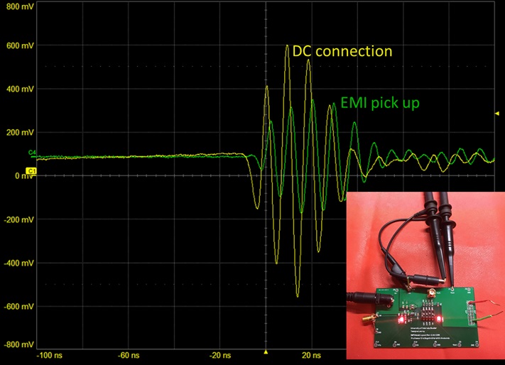
Figure 3. Comparing the direct DC measured voltage on the power rail and the EMI pickup noise with a similar probe with tips shorted together NOT connected to the power rail.
The voltage noise picked up from the probe not connected to the rail is nearly the same as the probe in contact with the rail, strongly suggesting the noise is all RF pickup.
So, what is the actual voltage noise on the rail? The only way to get a true measure is by probing the rail in a way that minimizes the loop area of the probe. This is why it is often a good idea to add a coax connection to the rail voltage if you want a true measure of the rail voltage noise.
Identifying artifact #2: reflections in the cable form unterminated ends
Connecting a coax cable to the SMA on the board, directly into the scope, allows a path less susceptible to EMI pick up. Figure 4 shows the measured voltage noise from the coax cable connection, compared to the 10x probe. While the EMI pick up amplitude is less, it is still present, and surprisingly enough, at a different frequency than the EMI pick up measured by the 10x probe!
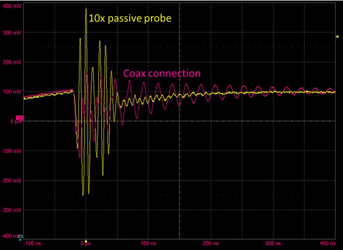
Figure 4. Measured voltage noise on the rail using a 10x passive probe and a direct coaxial connection into the scope both on 1 Meg input, AC coupled.
In addition, the ringing noise on the coax connection is a very high Q ringing, going on for dozens of cycles. How is it possible to measure different frequencies of EMI pick up from the same source?
This sort of ringing is often seen when we have a transmission line connection driven by a fast edge, low impedance source and with 1 Meg input at the scope. This is exactly what we have engineered. The way to eliminate this measurement artifact is to use 50 Ohms input at the scope.
Avoid the three problems with 50 Ohms scope input when measuring power rails
There are three problems using 50 Ohm input at the scope. If the input RMS voltage to the scope is larger than 5 V, there is the danger of dissipating too much power in the terminating resistor and damaging the scope.
In this specific rail, the voltage is only 3.3. V, so is not an issue. But if the rail were 5 V, this would put the measurement close to the edge of what might cause a problem. Any higher rail voltage could damage the scope.
The second problem is that there is no AC coupling on the 50 Ohm input impedance setting. To see small changes on the 3.3 VDC signal means the scale must be offset. On the 200 mV/div scale, the maximum offset on this specific scope, similar to scopes from many other vendors, with 50 Ohm input, is only 3.0 V. This makes it difficult to use a vertical voltage sensitivity scale any finer than 200 mV/div.
Finally, the third problem using a 50 Ohm input on the scope to measure this rail is that we have just connected a 50 Ohm load to the rail. At 3.3 V, this is a current load of 66 mA of current. This is significant when the rail is designed for only 500 mA.
Active probing to the rescue
To solve each of these problems, an active probe can be used. When designed specifically for power rail probing, they are often referred to as “rail probes.” The specific RP4030 used in this project has a DC blocking capacitor into the 50 Ohms of the scope to provide 50 Ohm termination for high frequency signals, but a parallel, low pass active amplifier circuit with +/- 30 V DC offset capability and 50k Ohms input impedance at low frequency.
This combination means, the coax is terminated at 50 Ohms, but the rail sees a high DC impedance. The probe loads the rail with 66 microApms, insignificant. The connection is coaxial from the board to the scope so there is minimal EMI pickup. And we can zoom in on any sensitivity scale and offset the DC voltage of the rail.
Figure 4 shows the final result of the measurement of the DC rail. In fact, the high-frequency noise on the power rail is less than 50 mV peak to peak, much less than the 1 V peak to peak the initial measurement suggested.
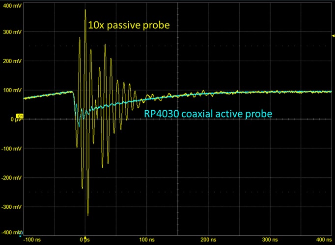
Figure 5. Comparison of the 10x probe and coaxial rail probe measuring the same power rail on the board.
Conclusion
While it is easy to perform a measurement, it is sometimes difficult to avoid common artifacts unless you know to anticipate them. This example illustrates two important artifacts in measuring voltage noise on SMPS power rails: (1) EMI pick-up noise from the large switching currents radiating from the board and (2) ringing noise in the coax cable connection between the low impedance of the power rail and the 1 Meg input to the scope.
The way to eliminate these and not load the rail with a 50 Ohm load is to first instrument your board with a coaxial connection and second to use an active rail probe to measure the power rail. This will eliminate the major sources of artifacts and enable you to see the voltage on the power rail that all the circuits using this rail will see, instead of measurement artifacts.