

One reason I enjoy attending a conference is the opportunity to browse presentations I would not ordinarily see. I always pick up something new and useful.
At this year’s IEEE EMC symposium in New Orleans, among my new insights were these:
Engineering Good Launches to 50 GHz is Hard
Jim Nadolny, from Samtec, as part of the IEEE P370 review, presented some guidelines for optimized fixture design. He showed an example of how very subtle features in the design of a coaxial launch can affect the quality of the launch. Figure 1 contains an example of the TDR response of two nominally identical 1.8 mm connector launches on a circuit board. One of them was much worse than the other.
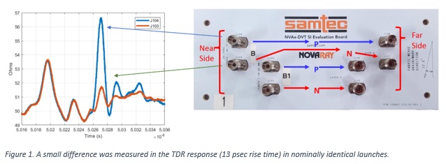
After careful forensic analysis, the root cause was traced to a 3.5 mil mis-registration of the signal via drill to the capture pad. Identically designed launches behaved differently due to their manufacturing variation. This was enough, confirmed in 3D full wave modeling, to create this small discontinuity. Using this knowledge, his team was able to re-design the launch to be less sensitive to a mis-registration.
The test vehicle after re-design showed a 10 GHz increase in the -10 dB return loss limit to this launch.
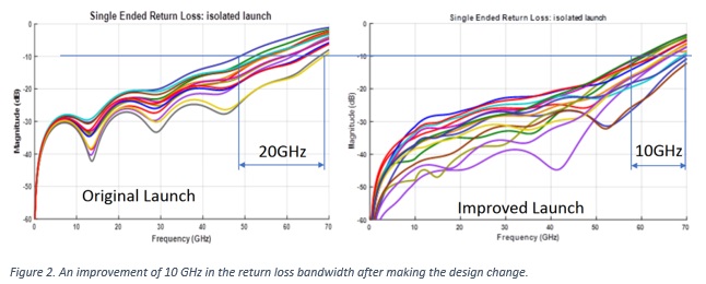
“A good launch to 50 GHz,” Nadolny said, “is about not just an optimized design, but one that is robust to normal manufacturing variations.”
Measuring a Battery’s Impedance is Tricky but Important
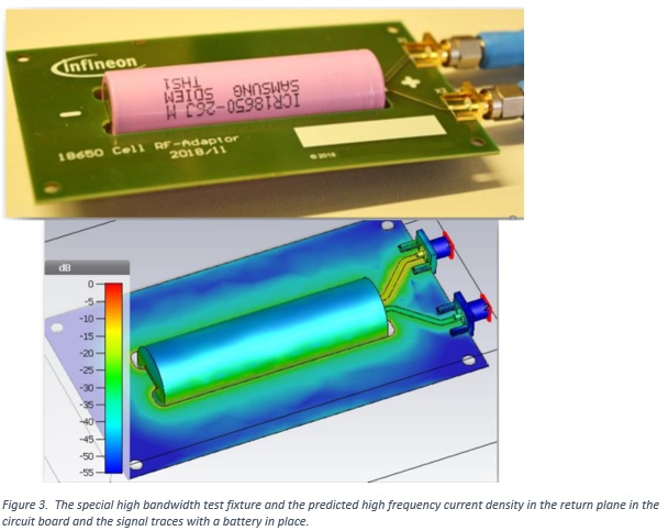
Thomas Landinger, a PhD student and engineer with Infineon, presented “A Novel Method for High Frequency Battery Impedance Measurements.” Impedance measurements of batteries generally are performed at low frequency, below 10 kHz. This is a standard technique to study the electrochemical processes in the battery. But with the proliferation of high-performance batteries in automotive applications, high bandwidth equivalent circuit models are needed to predict how the batteries will perform with complex inverter circuits and with imposed digital communications signals.
Landinger developed a novel fixture to mount a battery so its impedance can be measured with a 2-port VNA method, up to 1 GHz. Figure 3 shows an example of the circuit board fixture and the predicted current density.
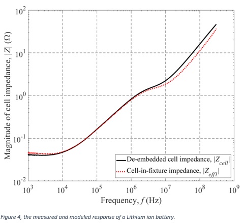
With the measurements, he was able to build a simple model for a Lithium ion battery based on its internal electrode geometry. Figure 4 shows the match between the simulated and measured response. The internal resistance of this cell was 40 mOhms, with total loop inductance, including the fixture of about 150 nH.
Rules for Grounding
Every year more than a dozen industry experts share their expertise in a series of tutorials. Todd Hubing usually presents his Grounding Tutorial.
If there is one message to remember from his session, it is Ground is not a signal return path.
Here are a dozen of his most important design rules for grounding:
Rules for grounding: (Ground is a conductor that serves as a voltage reference and never carries current.)
- Designate one location or one non-current-carrying metal structure as your zero-volt reference or ground.
- Be sure that all other metal structures including attached cables and large heatsinks do not deviate from the ground potential by more than an acceptable limit.
- For radiated emissions (10s of MHz and higher), this acceptable limit is on the order of 1 mV.
- For safety, the acceptable limit is generally on the order of 10s of volts.
Rules for current return routing
- Two circuits that operate at voltages or currents that differ by an order of magnitude or more should not share the same return trace or wire.
- At frequencies below 1 MHz, two circuits that operate at voltages or currents that differ by more than two orders of magnitude or more should not share the same return plane on a circuit board.
- At frequencies above 1 MHz, circuits can share the same return plane on a circuit board provided their currents do not overlap. (Remember, the return currents are confined to the region of the plane immediately below a microstrip trace.)
Suggestions for routing:
- Identify your ground structure (or your connection to the ground structure) and be sure it is the only ground that is large or connected to anything large!
- Don’t call current carrying nets “ground.” For example, refer to a current carrying analog reference net as “analog return.”
- Be aware of where your HF and LF currents are flowing!
- Isolate returns only when necessary to control the flow of low frequency currents.
- If you isolate two large conductors at low frequencies, be sure they are well connected at high frequencies.
These are some of the reasons to make the IEEE EMC Symposium an event to attend next year.