


This blog is part two of a three-part series. Please find part one here and part three here.
Measuring the Known DUT
Let’s continue our discussion from where we left off in our last blog. If you recall, after we defined how much CMRR is required to measure a 40 µΩ (2000 Amp) PDN with a 2-port probe, we said we would show you how to make a 40 µΩ impedance measurement with the 2-port probe.
Before making a 40 µΩ measurement, we need to create a DUT.
Figure 1 depicts the DUT that was created to support this low impedance measurement with the 2-port probe. However, when this DUT was made, it was not known precisely what the impedance of the copper on this PCB mount was. So how do we check this?
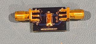 Figure 1. Depiction of 37 µΩ known DUT.
As shown by Figure 2, an accurate power supply is used to source 1 Amp through one cable connected to P2102A 2-port probe, which is connected to the DUT. Where the voltage drop across the DUT is measured through the other port on the P2102A 2-port probe, which is connected by another cable and to a 6.5-digit digital multimeter (DMM). The voltage produced by a 1 Amp current is equal to the resistance, which at 25C is 37 µΩ.
Before we measure our DUT with the VNA, we will need to make a second measurement of a short with a resistance that is much lower than our DUT, this is because the Bode 100 does not have a KNOWN SHORT calibration, and we do not have known DUT beyond DC. So Figure 3 depicts the same measurement with the power supply and DMM except the probe is contacting a pure solid, copper anode bar, which shows a value of 3.7 µΩ.
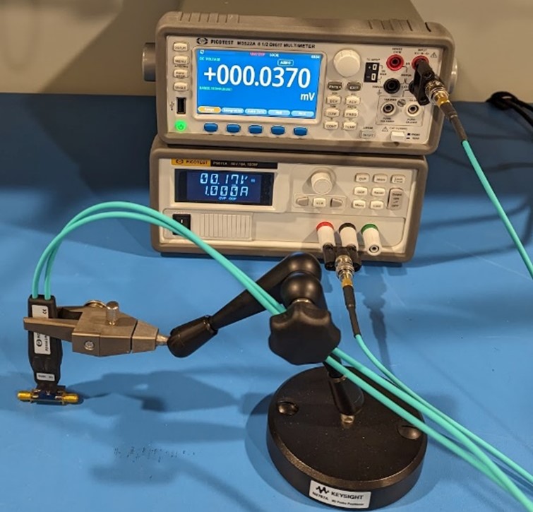 Figure 2. Measurement result with power supply, DMM, P2102A, and DUT.
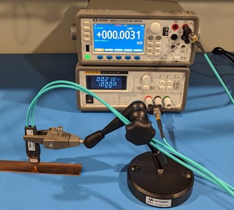 Figure 3. Measurement result with power supply, DMM, P2102A, and copper bar.
The 40 µΩ (2000 A) PDN Measurement Result
Now that we have created a baseline measurement of our DUT’s value, we are now ready to plug our VNA, connect our 2-port probe and isolator to measure the impedance. Figure 4 and Figure 5 depict our measurement setup using the Bode 100, P2102A, J2114A prototype isolator to measure our DUT and a copper bar.
 Figure 4. Measurement setup with Bode 100, P2102A 2-port probe, J2114A prototype isolator, and known DUT.
 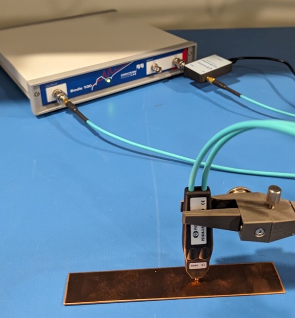 Figure 5. Measurement setup with Bode 100, P2102A 2-port probe, J2114A prototype isolator, and copper bar.
 Using Equation 1, an expression can be created within the Bode 100 to plot the impedance of our DUT.

The impedance of our DUT is plotted from the expression, shown in EQ(1), using the Bode 100 VNA, P2102A, and the J2114A prototype isolator is shown in Figure 6 as 34.2 µΩ at 50 Hz and 33.6 µΩ at 100 Hz.
If you recall, we measured the copper bar, which is our short, to be 3.7 µΩ using the power supply and the DMM. When we subtract that value from 37 µΩ we also measured with the power supply and DMM, this equates to a value of 33.3 µΩ, which is less than 1 µΩ (3%) difference from the result shown in Figure 6 at 50 Hz. This measurement can be challenging considering that the contact pressure from the probe, and the spring contact resistance of the P2102A probe, can all affect this measurement. This is one reason why a probe holder is used – to maintain constant pressure.
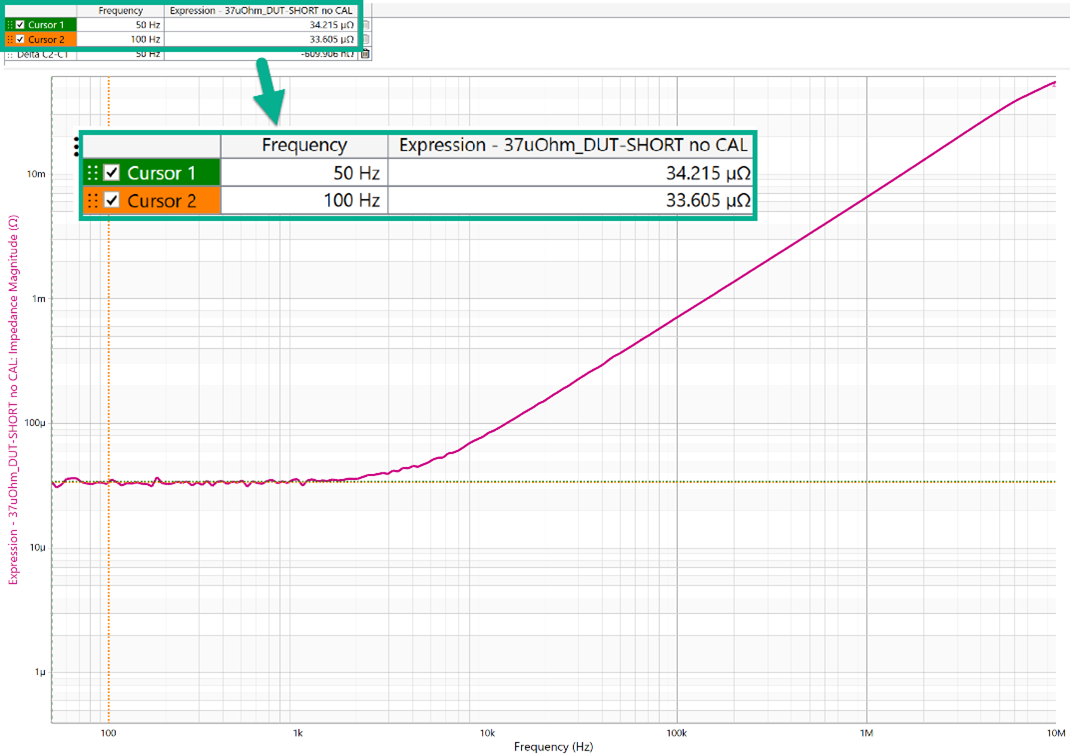 Figure 6. Measurement result of 37 µΩ DUT impedance measurement.
How Much CMRR Does Our Isolator Have?
In Figure 7, the CMRR result of the J2114A prototype isolator is shown. At close to DC a result of 111 dB is achieved, where our minimum target CMRR of 77.5 dB is seen at 13 kHz. Whereas the CMRR result achieved close to DC with the J2113A is 44 dB, this is almost 67 dB worse than the J2114A.
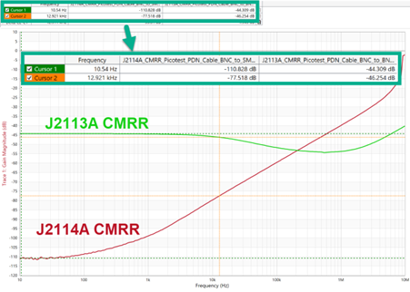 Figure 7. CMRR measurement result of Picotest J2114A prototype vs. J2113A with Bode 100.
Wrapping Up
In this two-part blog, we showed two key points:
- How to calculate the minimum CMRR with a PDN impedance measurement using a 2-port probe.
- That it is possible to measure a sub-40 µΩ impedance using a 2-port probe, when using an isolator that has sufficient CMRR.
Achieving sub-40 µΩ impedance measurements is challenging, but completely possible and realistic with the proper test equipment.
REFERENCES
- Pure Copper Anode Sheet, Amazon.
- S. M. Sandler, “How to Measure Ultra-Low Impedance (100uOhm and Lower) PDNs,” EDI CON, October 2018.
- A. K. Davis, S. M. Sandler, “The 2-Port Shunt-Thru Measurement and the Inherent Ground Loop,” EDI CON, October 2018.
- Bode 100 Vector Network Analyzer, Picotest.
- P2102A 2-Port Probe, Picotest.
- PDN Cable, Picotest.
- J2113A Semi-Floating Differential Amplifier, Picotest.