USB 3.x systems frequently use redriver devices located near the USB connector to clean up the signals. This allows impairments caused by the traces within the system to be hidden from the externally facing interface. The higher speed of USB4 standard has prompted a move to retimers and away from redrivers within USB-C systems for proper signal integrity.
Redriver devices are limiting analog amplifiers and fully recover the bit stream by using equalization and clock-data recovery. They then retransmit a fresh copy of the recovered data stream. Retimers reduce the jitter and retransmit the signal. Figure 1 shows a comparison of representative transmit-direction eye diagram that have been sent through a redriver versus a retimer.
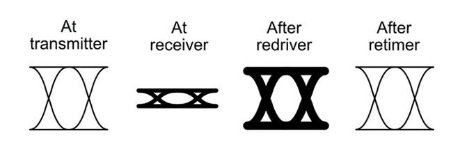
Figure 1: A comparison of redriver-retimer signal.
Jitter accumulation is the key factor that makes redrivers fail in real systems at higher speeds. To analyze a system design to see whether it will function well and meets the requirements of USB4, detailed signal integrity analysis must be undertaken.
The following steps can be taken:
Collect a set of S-parameters for each of various representative cables that will be connected to the USB-C connector. These can either come from measurement by a network analyzer or from the cable manufacturer or both. These sets should contain a mixture of losses. Representative losses for passive cables include 2.5, 5, 8 and 10 dBs. These roughly map to 0.2, 0.4, 0.8 and 1 meter in length. Your collection should also include cables that are at the edge of the specified parameters for skew and crosstalk. There should be a cable that is at the extreme bounds of all parameters at the same time. It is also important to include some cables that violate the specifications. Twelve-port S-parameter files are useful so that the crosstalk from two aggressors can be accounted for in the measurements. Retimers contained in active cables are treated as full endpoints. Active cables are modeled as concatenated full links with passive segments in between.
Collect a set of S-parameters for each of a wide variety of far-end systems. These systems should have a mix of trace lengths between the USB-C connectors and devices. These systems should have imperfections in terms of skew and crosstalk, both at and beyond the bounds of the specifications. Chip vendors often provide two-port IBIS AMI models of their devices and sometimes of reference platforms. If it is possible to get a bare board, the board’s S-parameters could also be measured by a network analyzer. These systems may have a mixture of redrivers and retimers. If retimers are used in a system, model it as a concatenation of full links. If retimers are used, the portion of the system behind the retimer can often be ignored because the link between the retimer and the endpoint chip may have plenty of margin.
Collect a set of S-parameters for the near-end system to be analyzed. This should accurately model each USB-C port separately. Some combination of vendor measurements and your measurements may be necessary. Any redrivers or retimers should be accurately modeled as detailed below. The segments before and after these devices should be modeled including effects such as crosstalk and skew. Again, it may be possible to ignore the link between a retimer and processor if this link is found to have plenty of margin.
The S-parameter sets for the various elements should be collected with care, using the same maximum frequency. Measurement effects should be carefully de-embedded. Any extrapolations should also be applied with great care.
Prepare a simulation model of the source and destination devices. On the transmitter side, this model should accurately account for the transmit swing, the transmit Signal to Noise and Distortion Ratio (SNDR), and the transmit package. It should have a method of setting the transmit equalizers automatically according to the channel used with some defined inaccuracy. On the receive side, this model should accurately account for the receive package, the input noise, the equalizers, and the sampling uncertainty caused by input jitter & by the operation of the clock-data recovery circuit. The model should have a method of setting the receive equalizers automatically according to the channel used with some defined inaccuracy.
A redriver model should be prepared. That model should have a gain element, an input noise source, and a transmit distortion model. This model should be correlated with the performance of actual devices. More sophisticated models can incorporate additional effects such as power supply noise impacts.
Next a retimer model should be prepared. The most straight-forward models look like the source and destination devices mounted in smaller packages. More sophisticated models can incorporate subtle effects such the impacts on the reference frequency when passed through chains of phase locked loops.
Purchase one of the commercially available analysis tools and see that personnel are trained and practiced in their use. We use Keysight ADS but other tools are fine as well. There is a long learning curve for these tools. The first series of simulations performed by any new group of engineers will inevitably be inaccurate due to missteps both small and large.
For each element individually, a series of specific compliance measurements must be taken at specific points as defined by the USB specifications and by other definitions of interest. These include items such as the total insertion loss for the host and the integrated return loss for cables. Given that USB4 and its compliance methodology is still emerging, it is reasonable to expect some flux on the details of these measurements.
Once the elements are measured, the performance of the system must be looked after in a more holistic manner than is defined by the specifications. Determine the target Bit Error Ratio (BER) that the system should operate at. Determine a suitable correction factor to add to the analysis to cover the collective negative impacts of small effects that are not otherwise covered.
Run the tools and determine the margin for each collection of source device, source traces, source redriver/retimer, further source trace & connector, passive/active cable, destination connector and trace, destination redriver/retimer, further trace, and destination device. Both directions must be simulated. This analysis will typically involve hundreds of runs and may take many hours of run-time. Find the combinations where the remaining margin becomes negative. Hopefully, these will not include some of the desired combinations. When retimers are used, this simulation burden in much reduced because the full link is broken up into a sequence of shorter links as shown in Figure 2 and 3.
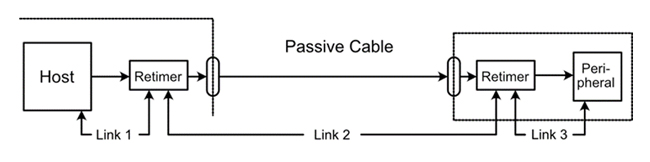
Figure 2: Retimers break the full link into three shorter links.

Figure 3: With active cables, the full link is broken up into five shorter links.
Redrivers are known to be problematic for USB4 because they do nothing to remove the jitter in the signal and drive out a noisier signal than retimers do as shown in Figure 4. The transmit jitter specification is typically the first to fail in these cases.

Figure 4: Redrivers leave the link subject to the concatenation of impairments.
For redrivers, the impact of all this analysis complexity presents another compelling reason to prefer the use of retimers. The links on the system sides of the retimers can often be ignored if they have plenty of margin, significantly simplifying the design.
Adding to the complexity, different ports on the same system are likely to have different performance for end-users when redrivers are used. For example, a port located in a far corner of a system may experience more errors than a port located in the middle as shown in Figure 5. If retimers are used near each USB-C port, the system will be much simpler to analyze and will have more consistent operation over a wider variety of use cases.
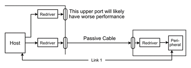
Figure 5: With redrivers, the USB-C port further from the host often has poorer performance.
Once systems are built, compliance at the USB-C connector can be measured in a variety of ways. Measurement is important to help control the manufacturing variance of systems and to debug problems in the lab or in the field. It is also important to help correlate the analysis techniques used to measured values.
A first method of measuring compliance is to build a compliance board that interfaces the USB-C to high-speed connectors over short, constant length traces. Coax cables are then used to connect these to a high-speed oscilloscope. Care must be taken to de-embed the board and the cables from the measurement.
A second method of measuring compliance is to create a paddle card that has a retimer device on it that contains eye-scope functionality. This retimer device can be placed very close to the USB-C connector to help minimize the need for de-embedding. Compliance tests can then be constructed using the eye scope and software. Vertical and horizontal bathtub curves can also be constructed. Internal eye-scopes can also be useful in the manufacturing test of both the devices and the systems that use them. The Matterhorn retimer from Kandou contains such an eye-scope.
About Brian Holden
Brian Holden is vice president of standards at Kandou. Previously, he served as president and fellow of the HyperTransport Consortium, chair of the market awareness and education committee for the Optical Internetworking Forum (OIF) and director of standards for PMC-Sierra (now Microsemi). Brian began his career as an electrical engineer at GTE. He received a Bachelor of Science degree in Electrical Engineering from the University of California, Davis and an MBA from Cornell. He is the author of “HyperTransport 3.1 Interconnect,” a biography of his great grandfather titled, "Charles W. Woodworth: The Remarkable Life of U.C.’s First Entomologist,” and the forthcoming book titled “Chord Signaling.” He has 49 U.S. Patents.