Semiconductor ICs are the key components of complex electronic circuits. In countless technical applications, these small processing, control and memory components help master the great challenges of our time. Global trends such as the digital transformation of society and the economy require highly integrated ICs able to process ever higher data rates. To support this pace of development in the semiconductor industry, measurement systems must also extend their capabilities to ever higher frequencies.
The semiconductor, automotive and mobile communications sectors act as technology drivers for interconnects, as they are creating applications that use frequencies well into E-Band. Familiar examples of applications between 60 and 90 GHz include advanced driver assistance systems using radar for active cruise control, the PAM4 high speed data standard for 400G Ethernet and 5G and 6G infrastructure for mobile communications.
Responding to these trends, HUBER+SUHNER has developed a precision multicoax test solution for the high speed digital testing (HSDT) market. The MXPM90 reliably measures signals from DC to 90 GHz, while taking up only a small footprint on the board. The MXPM90’s broadband coverage and high signal integrity are each a prerequisite for the strength of the multicoax connector system, which provides an almost ideal interconnect from DC through 90 GHz.
HIGH FREQUENCY, HIGH DATA RATES
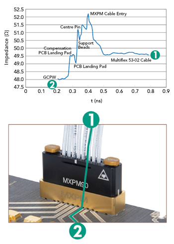
Figure 1 TDR measurement of a typical transition from a PCB to MXPM system.
When a new generation of ICs with data rates of 112 Gbps completes design simulation, it is fabricated on a wafer, with wafer probing used for the first electrical tests. The wafer is then cut and the individual ICs are packaged and mounted on a printed circuit board (PCB) for evaluation. Benchtop testing of the prototype requires a setup and test system that guarantees accurate and repeatable measurements. The interconnect from the test system to the IC must be transparent, i.e., with low insertion loss, low VSWR and tight phase matching among channels and consistent performance across the full operating bandwidth of the system. The measurements must be repeatable when the connectors are plugged and unplugged over the lifetime of the setup. The size of the interconnect is also important, i.e., how close the measurement system can be to the IC to minimize line losses on the PCB. These are the key considerations when designing a test setup and its interconnects.
Addressing these requirements, the MXPM90 from HUBER+SUHNER consists of a PCB socket, optimized for low interference signal transmission, and the single interconnect cable assemblies, which are electrically and mechanically stable but still exhibit excellent flexibility. The combination provides a 90 GHz connection from the PCB to the measurement system or to another PCB connector. HUBER+SUHNER produces both the connector and proprietary cable internally, optimizing them to be compatible.
The MXPM90 breakout assemblies have 1 mm connectors, which are designed for 110 GHz, with the complete assembly specified to 90 GHz. The predecessor MXPM70 uses 1.85 mm connectors, which have an upper frequency of 70 GHz. Normally, the tracks on the PCB have high insertion loss at mmWave frequencies, so the design goal is minimizing the track length and moving into a coaxial structure as soon as possible, meaning the connectors should be located close to the IC. Designed to minimize this distance, the MXPM90 has a short 2.54 mm center-to-center spacing between adjacent channels.
SIGNAL INTEGRITY
The MXPM90 offers excellent signal integrity to 90 GHz, minimizing noise, reflections, distortion and losses. Figure 1 shows the time domain reflectometry (TDR) response of a typical impedance transition from a PCB to an MXPM cable assembly. The PCB signal trace (designated as 2 in the figure) is a coplanar line with w = 0.28 mm and gap = 0.2 mm fabricated on a 5 mil thick Rogers 3003 substrate with εr = 3.

Figure 2 Plug cycle test setup.
The signal trace on the evaluation board shown in the figure has an impedance of approximately 48 Ω, with a tolerance of ±5 Ω due to manufacturing variation. It ends in a landing pad where the inner conductor pin of the MXPM presses. The low impedance—therefore capacitive behavior—of the pad is compensated for with a constriction in the signal track. The deflections in the TDR diagram show the electrical discontinuities of the MXPM cable assembly. The highest value, which also poses the highest uncertainty, is at the transition to the Multiflex-53 cable, which has an impedance of about 49.5 Ω, with a tolerance of ±2 Ω from the manufacturing process. Optimized for high frequency performance, the maximum ripple is 2.5 Ω.
Phase matching among the channels of a single interconnect assembly have an electrical length tolerance of only ±1 ps. Keeping this low was an integral part of the MXPM90 design.
REPRODUCIBLE
A plug cycle test demonstrates the reproducibility and durability of the MXPM series. In the test, a single channel of the MXPM CAY is connected to a special coaxial adapter, which presses the two cable connectors together until they reach a defined reference surface and make the electrical connection (see Figure 2). During this process, the outer conductor crown of the MXPM male single channel slides into the insertion cone of the MXPM female single channel and the spring pin of the MXPM male connector presses onto the flat inner conductor of its counterpart.
To document the durability of this MXPM coupling, several MXPM single channels were connected 50,000 times, with the S-parameters measured after every 50 couplings, yielding 1,000 total S-parameter measurements during the 50,000 cycles. Figure 3 shows the wear on the connector interfaces after 50,000 cycles. Across the 1,000 data sets, the insertion loss change was less than ±0.1 dB (see Figure 4a), although it increases at the upper frequencies as the number of cycles increases. Combining the data from the 1,000 measurements, Figure 4b shows the mean and ±6 sigma values of insertion loss versus frequency for a 0.66 m length.

Figure 3 Wear after 50,000 plug cycles: female (a) and male (b) interfaces.
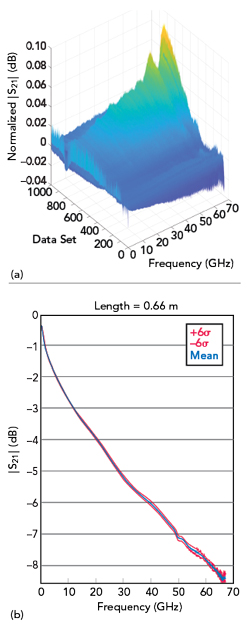
Figure 4 20 MHz to 67 GHz insertion loss vs. measurement count, normalized to the first measurement (a). Mean and ±6 σ values of the insertion loss vs. frequency, combining all 1,000 measurements (b).
PROVEN HEIRTAGE
The 90 GHz coverage of the MXPM90 is the latest extension of HUBER+SUHNER’s proven MXPM multicoax line, which has been used in various markets for over a decade. The higher frequency connector system supports highly accurate and reliable measurements of both digital and mmWave signals, and the coaxial design of the latest version of MXPM both extends frequency coverage and enhances shielding and signal integrity. As the direct successor to the MXPM70, the MXPM90 retains the features that have made the MXPM series well respected in the industry: electrical performance, easy handling and high quality. For example, the MXPM has a magnetic locking mechanism enabling “plug and play”—a consistent transition between the module and the PCB socket every time it is plugged in, which is unique in the HSDT market. Another feature is automatic interface protection to protect the contacts from mechanical damage as soon as the connector is disconnected.
SUMMARY
The semiconductor, automotive and mobile phone sectors are driving IC development. To meet the demands of the industry for testing ever higher data rates and frequencies, HUBER+SUHNER has developed the MXPM90. Based on a new multicoax connector system, the Swiss-based technology company can offer all industries a nearly “future-proof” test solution.
HUBER+SUHNER AG
Herisau, Switzerland
www.hubersuhner.com
Semiconductor ICs are the key components of complex electronic circuits. In countless technical applications, these small processing, control and memory components help master the great challenges of our time. Global trends such as the digital transformation of society and the economy require highly integrated ICs able to process ever higher data rates. To support this pace of development in the semiconductor industry, measurement systems must also extend their capabilities to ever higher frequencies.
The semiconductor, automotive and mobile communications sectors act as technology drivers for interconnects, as they are creating applications that use frequencies well into E-Band. Familiar examples of applications between 60 and 90 GHz include advanced driver assistance systems using radar for active cruise control, the PAM4 high speed data standard for 400G Ethernet and 5G and 6G infrastructure for mobile communications.
Responding to these trends, HUBER+SUHNER has developed a precision multicoax test solution for the high speed digital testing (HSDT) market. The MXPM90 reliably measures signals from DC to 90 GHz, while taking up only a small footprint on the board. The MXPM90’s broadband coverage and high signal integrity are each a prerequisite for the strength of the multicoax connector system, which provides an almost ideal interconnect from DC through 90 GHz.
HIGH FREQUENCY, HIGH DATA RATES
Figure 1 TDR measurement of a typical transition from a PCB to MXPM system.
When a new generation of ICs with data rates of 112 Gbps completes design simulation, it is fabricated on a wafer, with wafer probing used for the first electrical tests. The wafer is then cut and the individual ICs are packaged and mounted on a printed circuit board (PCB) for evaluation. Benchtop testing of the prototype requires a setup and test system that guarantees accurate and repeatable measurements. The interconnect from the test system to the IC must be transparent, i.e., with low insertion loss, low VSWR and tight phase matching among channels and consistent performance across the full operating bandwidth of the system. The measurements must be repeatable when the connectors are plugged and unplugged over the lifetime of the setup. The size of the interconnect is also important, i.e., how close the measurement system can be to the IC to minimize line losses on the PCB. These are the key considerations when designing a test setup and its interconnects.
Addressing these requirements, the MXPM90 from HUBER+SUHNER consists of a PCB socket, optimized for low interference signal transmission, and the single interconnect cable assemblies, which are electrically and mechanically stable but still exhibit excellent flexibility. The combination provides a 90 GHz connection from the PCB to the measurement system or to another PCB connector. HUBER+SUHNER produces both the connector and proprietary cable internally, optimizing them to be compatible.
The MXPM90 breakout assemblies have 1 mm connectors, which are designed for 110 GHz, with the complete assembly specified to 90 GHz. The predecessor MXPM70 uses 1.85 mm connectors, which have an upper frequency of 70 GHz. Normally, the tracks on the PCB have high insertion loss at mmWave frequencies, so the design goal is minimizing the track length and moving into a coaxial structure as soon as possible, meaning the connectors should be located close to the IC. Designed to minimize this distance, the MXPM90 has a short 2.54 mm center-to-center spacing between adjacent channels.
SIGNAL INTEGRITY
The MXPM90 offers excellent signal integrity to 90 GHz, minimizing noise, reflections, distortion and losses. Figure 1 shows the time domain reflectometry (TDR) response of a typical impedance transition from a PCB to an MXPM cable assembly. The PCB signal trace (designated as 2 in the figure) is a coplanar line with w = 0.28 mm and gap = 0.2 mm fabricated on a 5 mil thick Rogers 3003 substrate with εr = 3.
Figure 2 Plug cycle test setup.
The signal trace on the evaluation board shown in the figure has an impedance of approximately 48 Ω, with a tolerance of ±5 Ω due to manufacturing variation. It ends in a landing pad where the inner conductor pin of the MXPM presses. The low impedance—therefore capacitive behavior—of the pad is compensated for with a constriction in the signal track. The deflections in the TDR diagram show the electrical discontinuities of the MXPM cable assembly. The highest value, which also poses the highest uncertainty, is at the transition to the Multiflex-53 cable, which has an impedance of about 49.5 Ω, with a tolerance of ±2 Ω from the manufacturing process. Optimized for high frequency performance, the maximum ripple is 2.5 Ω.
Phase matching among the channels of a single interconnect assembly have an electrical length tolerance of only ±1 ps. Keeping this low was an integral part of the MXPM90 design.
REPRODUCIBLE
A plug cycle test demonstrates the reproducibility and durability of the MXPM series. In the test, a single channel of the MXPM CAY is connected to a special coaxial adapter, which presses the two cable connectors together until they reach a defined reference surface and make the electrical connection (see Figure 2). During this process, the outer conductor crown of the MXPM male single channel slides into the insertion cone of the MXPM female single channel and the spring pin of the MXPM male connector presses onto the flat inner conductor of its counterpart.
To document the durability of this MXPM coupling, several MXPM single channels were connected 50,000 times, with the S-parameters measured after every 50 couplings, yielding 1,000 total S-parameter measurements during the 50,000 cycles. Figure 3 shows the wear on the connector interfaces after 50,000 cycles. Across the 1,000 data sets, the insertion loss change was less than ±0.1 dB (see Figure 4a), although it increases at the upper frequencies as the number of cycles increases. Combining the data from the 1,000 measurements, Figure 4b shows the mean and ±6 sigma values of insertion loss versus frequency for a 0.66 m length.
Figure 3 Wear after 50,000 plug cycles: female (a) and male (b) interfaces.
Figure 4 20 MHz to 67 GHz insertion loss vs. measurement count, normalized to the first measurement (a). Mean and ±6 σ values of the insertion loss vs. frequency, combining all 1,000 measurements (b).
PROVEN HEIRTAGE
The 90 GHz coverage of the MXPM90 is the latest extension of HUBER+SUHNER’s proven MXPM multicoax line, which has been used in various markets for over a decade. The higher frequency connector system supports highly accurate and reliable measurements of both digital and mmWave signals, and the coaxial design of the latest version of MXPM both extends frequency coverage and enhances shielding and signal integrity. As the direct successor to the MXPM70, the MXPM90 retains the features that have made the MXPM series well respected in the industry: electrical performance, easy handling and high quality. For example, the MXPM has a magnetic locking mechanism enabling “plug and play”—a consistent transition between the module and the PCB socket every time it is plugged in, which is unique in the HSDT market. Another feature is automatic interface protection to protect the contacts from mechanical damage as soon as the connector is disconnected.
SUMMARY
The semiconductor, automotive and mobile phone sectors are driving IC development. To meet the demands of the industry for testing ever higher data rates and frequencies, HUBER+SUHNER has developed the MXPM90. Based on a new multicoax connector system, the Swiss-based technology company can offer all industries a nearly “future-proof” test solution.
HUBER+SUHNER AG
Herisau, Switzerland
www.hubersuhner.com