
Figure 7 shown the eye density plots for these two cases.

As can be seen, though the CS IR with AAF has reduced high frequency aliasing, its eye density plot has misleading fidelity.
Example 2: Tx with IBIS buffer and Tx router assembly output both defined with S-parameters with maximum frequency at 20 GHz and with 7.5 dB loss at Nyquist (10 GHz).
Figure 8 shows the CS IR in the time domain and frequency domain without and with AAA.
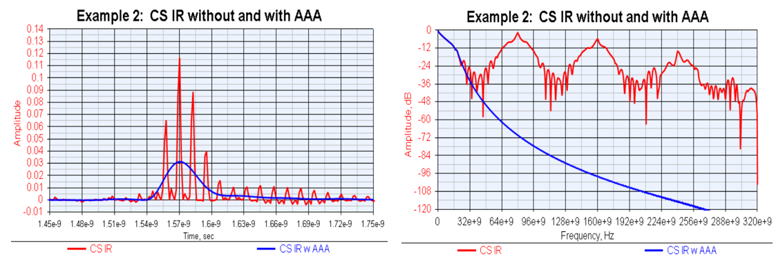
Figure 8. Example 2: CS IR in time (left)/frequency (right) domains without and with AAA.
As can be seen, there is a lot of high frequency aliasing in the IR. However, the IR w AAA has no high frequency aliasing and has no additional processing time delay.
Figure 9 shows the CS IR eye density plots without and with AAA.
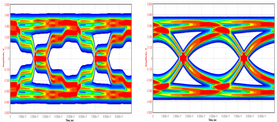
As can be seen, the IR eye density without AAA has significant high frequency aliasing effects that make the eye density unusable. The IR with AAA has a much cleaner and usable eye density plot.
Example 3: Tx with IBIS buffer and Tx router assembly output and channel passive cable all defined with S-parameters with maximum frequency at 20 GHz and with 21 dB loss at Nyquist (10 GHz).
Figure 10 shows the CS IR in the time domain and frequency domain without and with AAA.
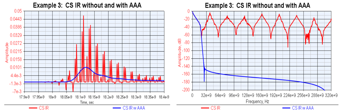
As can be seen, there is a lot of high frequency aliasing in the IR. However, the IR w AAA has no high frequency aliasing and has no additional processing time delay.
With this high loss channel, the eye is closed, and the eye density plots are not shown here.
The discussion above was focused on SerDes systems that used a pass-through Rx IBIS-AMI model since the test points of interest were before any Rx circuit as is typical as is required per various industry standards. The examples above are for test cases at the Tx IBIS buffer output, the Tx router assembly output and the output of a far end passive cable before the receiver.
These examples show the effects of high frequency aliasing and the use of AAA to eliminate those high frequency aliasing effects without compromise on the inherent S-parameter based channel.
In all examples, the AAA process matches the CS IR characteristics below the maximum S-parameter frequency (20 GHz in this case) and reformulated the characteristics above this frequency to eliminate high frequency aliasing while retaining a causal time domain response.
As has been mentioned, when an Rx IBIS-AMI model is used in which the Rx CTLE attenuates the high frequency aliasing, then this AAA approach is not needed.
Anti-Aliasing Algorithm (AAA) Discussion
The AAA has been in use for over 10 years with the technology from SerDesDesign.com with S-parameter data. It has been used to provide free high quality channel simulations and free tools for overcoming inherent S-parameter file limitations.
S-parameter data, though measured on physical devices, is non-causal in the time domain due to limited spectral bandwidth, discrete spectrum frequencies, and possible measurement noise. All time domain tools that use S-parameter data need to correct for these non-causal/non-physical effects in the S-parameter data to obtain meaningful causal time domain representation of the frequency domain data. Unfortunately, many companies take a frequency domain to time domain conversion approach that can result in undesirable high frequency aliasing.
One approach used by Keysight Technologies that does not result in high frequency aliasing is described in [7]. The Keysight approach and AAA have similarities and differences.
They both rely on extrapolating the S-parameter magnitude data beyond the maximum S-parameter frequency (F-smax) to the desired sampling Nyquist frequency (F-max). In our examples above the S-parameter maximum frequency was 20 GHz and the sampling Nyquist frequency was 20e9*32/2 = 320 GHz.
They differ in their extrapolation approach. The Keysight approach uses a 4th order polynomial to extrapolate the data from F-smax to F-max. AAA replies on extrapolating the final slope of the S-parameter data and deriving the phase based on a scientific approach.
They both rely on using the Kramers-Kronig relations which state the real and imaginary parts of a causal response are related by the following Hilbert transforms:

Where:
- u and v are real and imaginary parts of the spectrum
- P is the Cauchy principal value.
However, they differ in the approach used to convert the extrapolated data to causal data.
The Keysight approach relies on an iterative approach for optimizing the extrapolated data with a 4th order polynomial to result in a minimum in the error between the Hilbert transform of the real spectrum and the imaginary part of the extrapolated data.
AAA does not rely on any iterative approach. Instead, it derives the phase in the extrapolated region from the magnitude response. As the above Kramers-Kronig relations show, the real and imaginary parts of a causal response are related. Similarly, it can also be shown that under certain conditions the magnitude and phase of a causal response are related. Such a relationship shows that phase shift is obtained by integrating the product of the slope of the logarithmic magnitude plot with a weighting factor that decreases as the integration frequency is further from the evaluation frequency. The magnitude and phase are further adjusted to ensure that the requirements of the Kramers-Kronig relations are met. This is not an iterative process.
AAA has been in use for over 10 years with technology from SerDesDesign.com for use in converting S-parameter data to its equivalent causal representation in the time domain. AAA preserves the fidelity of the S-parameters up to their highest frequency while eliminating high frequency aliasing at higher frequencies with no added delay.
Conclusion
HSD transmit (Tx) and receive (Rx) circuits are modeled as IBIS-AMI models per the IBIS standard which are used with associated SerDes channels in SerDes channel simulators to evaluate their system margins. Oftentimes, the SerDes channel is defined with S-parameters which may result in the channel simulator modeling the channel with an IR that has excessive high frequency aliasing. An original and better anti-aliasing process was defined for use in CSs to eliminate the negative effects of high frequency aliasing without compromising the integrity of the channel characterization. The process preserves the fidelity of S-parameters up to their highest frequency while eliminating high frequency aliasing at higher frequencies with no added delay.
This paper first gave an overview of high frequency aliasing issues in context with industry standards compliance testing, SerDes systems examples were presented without and with the proposed AAA, and then the AAA was discussed.
This paper showed an effective approach (AAA) to eliminate high frequency aliasing without compromising the inherent characteristics in S-parameter based channels.
With AAA, any channel simulator can remove high frequency aliasing and provide their users a better environment for SerDes system simulation.
Acknowledgment
Acknowledgment is given to Blake Gray and Silicon Creations for use of their CS tool for channel simulation.
References
- Mayder, R., et al. (2015). IBIS-AMI Model Simulations Over Six EDA Platforms [1-96]. DesignCon 2015.
- Baprawski, John. SerDes Channel Impulse Modeling with Rambus. September 24, 2016.
- Baprawski, John.SerDes Channel Impulse Modeling with SignalMetrics. September 24, 2016.
- Baprawski, John. May 17, 2022. Overcoming Signal Integrity Channel Modeling Issues. Signal Integrity Journal.
- Universal Serial Bus 4 (USB4™) Router Assembly Electrical Compliance Test Specification. USB Implementers Forum, Inc. 2021.
- VESA DisplayPort™ PHY Compliance Test Standard. Video Electronics Standards Association. September 14, 2007.
- Keysight Data Integrity Check and Enforcement