
When two coplanar parallel traces run in close proximity over the coupled length, as shown in Figure 1, they are electromagnetically coupled together.
When two complimentary signals are transmitted, there is mutual electromagnetic coupling defined by amount of mutual inductance and capacitance. This is known as differential signaling. The differential impedance, (Zdiff), is the instantaneous impedance of a pair of transmission lines.
The impedance of each trace, when driven differentially, is known as the odd-mode impedance (Zodd). Conversely, when each trace is driven with the same polarity, the impedance of each trace is known as the even-mode impedance (Zev).
Differential impedance is simply twice the odd-mode impedance:
Equation 1
When Zodd = Zev, the traces are deemed to be uncoupled and there will be no crosstalk (XTalk). The characteristic impedance (Zo) of a single trace, in isolation, is equal to the geometric average (Zavg) of Zodd and Zev. When Zodd and Zev are not equal, there will be some level of XTalk, depending on the space between traces. In this case, Zo is approximately equal to Zav and is given as:
Equation 2
Crosstalk
There are two types of XTalk generated; Near-End (NEXT), or backwards XTalk, and Far-End (FEXT), or forward XTalk.
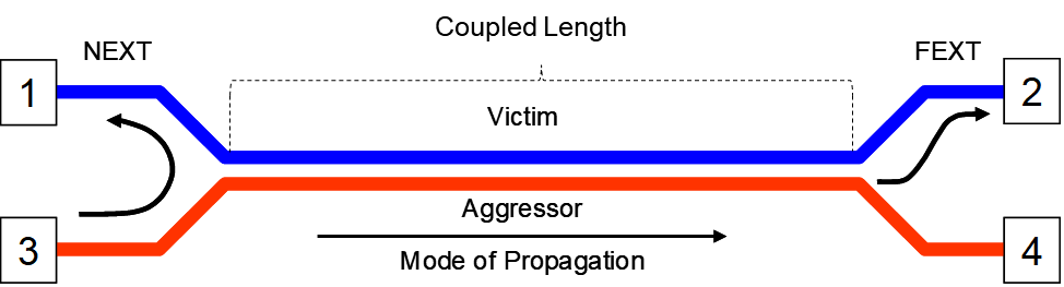
Figure 1. Illustration of NEXT and FEXT. As the aggressor signal propagates from port 3 to port 4, Near-End XTalk appears on port 1 and Far-End XTalk appears on port 2 after one time delay (TD) of the interconnect.
NEXT
Refer to Figure 1. Through electromagnetic coupling, NEXT voltage (Vb) is related to the coupled current through a terminating resistor (not shown) at port 1; when driven by an aggressor voltage (Va) at port 3. When port 1 is terminated, the backward XTalk coefficient (Kb) is defined by:
Equation 3

Where:
Vb = the voltage at port 1
Va = the peak voltage of the aggressor at port 3
The general signature of the NEXT waveform, for a gaussian step aggressor, is shown in Figure 2. Va is the aggressor voltage at port 3 of Figure 1. Vb is the NEXT voltage at port 1. The NEXT voltage continues to increase in response to the rising edge of the aggressor until it saturates after the aggressor’s rise-time. The green waveform (VaFE) is the aggressor voltage at port 4 after one time delay (TD). The duration of Vb waveform lasts for 2TD of the coupled length.
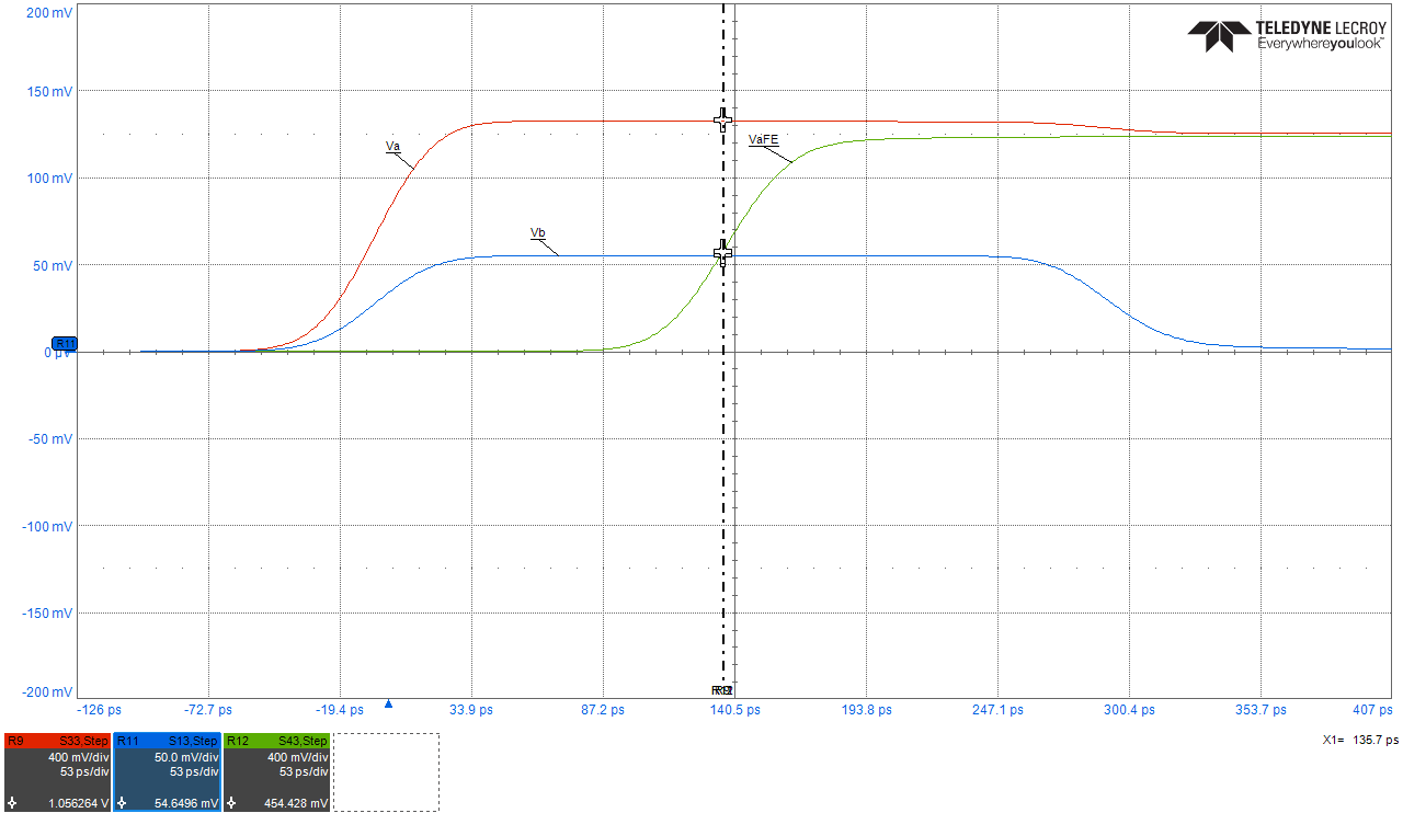
Figure 2. NEXT voltage signature, Vb in response to a gaussian step aggressor, Va. The duration of NEXT is equal to 2TD of the coupled length. VaFE is the aggressor voltage shown after one TD. simulated with Teledyne Lecroy WavePulser 40iX software.
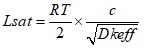
When TD is equal to one-half of the linear risetime, the NEXT voltage becomes saturated. The minimum length to reach saturation is known as the saturated length (Lsat), and is given by [1]:
Equation 4
Where:
Lsat = the saturation length for near-end cross talk in inches
RT = linear risetime to reach Va in ns
c = the speed of light = 11.8 in nsec
Dkeff = the effective dielectric constant surrounding the trace.
For example, a signal with a linear RT of 0.1 nsec, to reach an aggressor voltage of 1V using FR4 material, with a Dkeff of 4, the saturation length in stripline is:
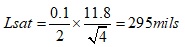
Important note: In PCB stripline construction, Dkeff is the Dk of the dielectric mixture of core and prepreg. But in microstrip, without solder mask, Dkeff is the mixture of Dk of air and Dk of the substrate. It is very difficult to predict the exact Dkeff in microstrip without a field solver, but a good approximation can be obtained by [3]:
Equation 5
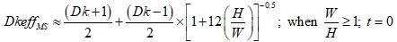
Where:
DkeffMS = effective dielectric constant surrounding the trace in microstrip
Dk = dielectric constant of the material
H = height of dielectric
W = trace width
t = trace thickness
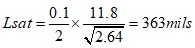
For example, a signal with a linear RT of 0.1 ns, to reach an aggressor voltage of 1V and DkeffMS of 2.64, the saturation length in microstrip is:
If the coupled length (Lcoupled) is less than Lsat, the NEXT voltage will peak at a value less than the saturated NEXT voltage. The actual NEXT voltage, Vb, is scaled by the ratio of coupled length to saturation length and is given by [1]:
Equation 6
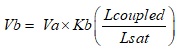
For example, for a coupled of length of 100 mils and saturated length of 295 mils, NEXT voltage will be (100/295) or 33.9% of the saturated NEXT voltage.
NEXT vs Coupled Length in Stripline
Figure 3 plots NEXT voltage vs coupled lengths for 100 mils, 295 mils and 590 mils representing less than, equal to and greater than Lsat respectively. For a coupled stripline geometry modeled with Polar SI9000 field solver (Figure 3B) Kb is 0.065.
Each length was simulated in Polar Si9000 and touchstone files were imported into Keysight PathWave ADS software for further analysis. The results are plotted in Figure 3A.
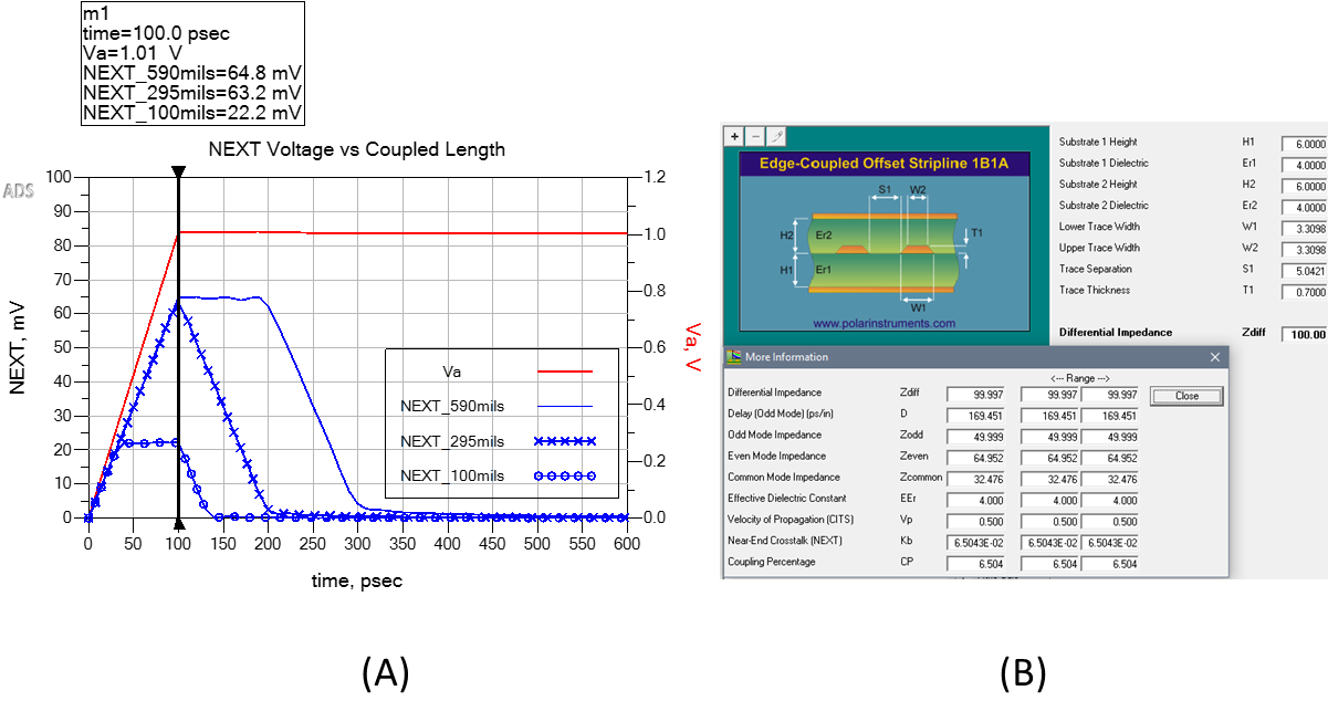
Figure 3. Example of NEXT voltage vs couple lengths of 100 mils, 295 mils and 590 mils in stripline. Modeled with Polar Si9000 and simulated with Keysight PathWave ADS.
As can be seen, using a 1V aggressor with a linear risetime of 0.1 ns and a saturated length of 295 mils, the NEXT voltage is 63.2 mV, compared to full saturated NEXT voltage of 64.8 mV. With a coupled length of 100 mils, NEXT voltage saturates at 22.2 mV, for the duration of the aggressor’s risetime, compared to 22.03 mV predicted by Equation 6 [1].