
Ethernet FEC encoder and decoder interface and coding schemes
In the previous section, we only focused on symbol multiplexing mode as shown in Figure 1. In this section other coding schemes like bit-multiplexing and codeword interleaving will be added.
PMA bit multiplexing
As today’s FEC for 100 GbE (2x50 Gb/s), PMA 2:1 bit multiplexing is deployed as shown in Figure 10 and defined in IEEE802.3bs section 120.5.2 [2]. Figure 11 shows how a group of bits encode to PAM4 symbols and RS symbols for this case. Unlike symbol multiplexing, lsb and msb bits of a PAM4 symbol belong to different RS symbols in 2:1 bit multiplexing. So a very short error pattern like 2 PAM4 symbols in a row could easily cause two RS symbols in error. Thus the bit multiplexing could harm the FEC performance.
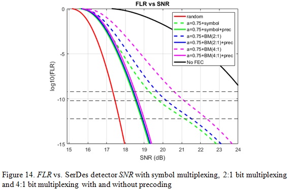
For 100 GbE with 100 Gb/s per lane interface, the bit multiplexing could be 4:1 instead of 2:1 as shown in Figure 12. Compared with 2:1 bit multiplexing, we can see that a short burst error can easily cause 4 RS symbols in error for 4:1 bit multiplexing. Therefore, we expect further FEC performance degradation by using 4:1 bit multiplexing. It is proven by the analysis results in Figure 13 and 14 for burst error model with a=0.75. We can see that for 100 GbE FLR target 6.2e-10 (equivalent to BER 1e-12), compared with symbol multiplexing scheme, 2:1 bit multiplexing has 0.41dB FEC coding gain degradation while 4:1 bit multiplexing has 1.32dB degradation. However, pre-coding can wipe out the coding gain delta between the cases of with and without bit multiplexing. Therefore, precoding is a necessary function to alleviate the bit-multiplexing penalty for a burst error channel with large error propagation factor a.
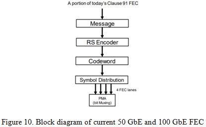
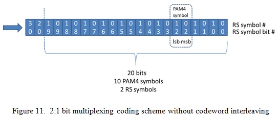

Figure 12. 4:1 bit multiplexing coding scheme without codeword interleaving

Codeword interleaving
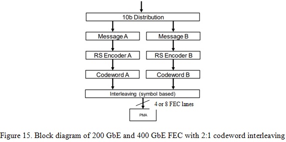
As today’s FEC for 200 GbE and 400 GbE with 50 Gb/s per lane, 2:1 codeword interleaving is deployed with a checkerboard order as in Figure 119-10 and 119-11 in [2]. Figure 15 illustrates how 2:1 codeword interleaving will apply to 200 GbE and 400 GbE with 100 Gb/s per lane interface.
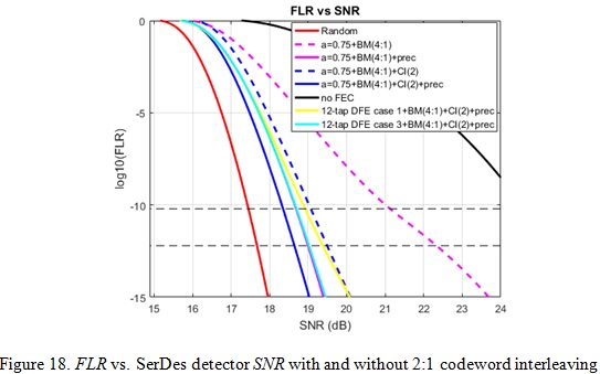
Figure 16 shows how a group of bits encode to PAM4 symbols and RS symbols for 4:1 bit multiplexing and the 2:1 codeword interleaving coding scheme. The block colors (blue and red) represent which codeword it belongs to. The purpose of codeword interleaving is to mitigate the error propagation by breaking a long burst error into two separate codewords and thus to improve the coding gain. From the analysis results in Figure 17 and 18 for a burst error model with a=0.75, we can see that for the 200/400 GbE FLR target 6.2e-11 (equivalent to BER 1e-13) 2:1 codeword interleaving provides 2.06 dB more coding gain than no codeword interleaving for the cases without precoding. With pre-coding the delta between those two is getting smaller, but still 0.45dB coding gain with 2:1 codeword interleaving is observed.


Summary for 100/200/400 GbE with 100 Gb/s per lane interface
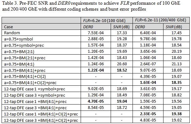
Table 3 shows FEC performance for 100 GbE and 200/400 GbE with a 100 Gb/s interface with different coding schemes and burst error profiles. For 100 Gb/s Ethernet, the target FLR is 6.2e-10. There is no codeword interleaving but there would be PMA 4:1 bit multiplexing which may harm KP4 FEC performance.
For 200 Gb/s and 400 Gb/s Ethernet, the target FLR is 6.2e-11. Two codewords are interleaved in a checkerboard pattern and there would be PMA 4:1 bit multiplexing. At the SerDes PHY level precoding can be enabled or disabled. Random error, 1-tap DFE and 12-tap DFE are considered for the analysis.
From the results we can conclude:
- Compared with the random error case, DFE error propagation degrades KP4 FEC coding gain. A multiple-tap DFE could be worse than a 1-tap DFE.
- Precoding is a necessary function to mitigate the bit-multiplexing penalty for burst error channel with large error propagation factor a.
- PMA 4:1 bit multiplexing harms KP4 FEC performance while 2:1 codeword interleaving helps.
- DFE architecture plays an important role for FEC performance. If a 1-tap DFE is used, DER0 requirements to achieve FLR performance are higher than 1e-4 for both 100 GbE and 200/400 GbE even with the worst case of error propagation a=0.75. However, if a 12-tap DFE with maximum DFE tap coefficients (defined in 802.3cd) is used, DER0 requirement is tightened to the order of 1e-5.
FEC for the multi-part link
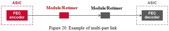
In this section, let’s extend the FEC analysis to the multi-part link. Figure 19 and Figure 20 illustrate the differences between the single part link where a FEC is dedicated to the link and the multi-part link where a FEC is shared between 2 or more parts of the link. For a multi-part link with two chip-chip or chip-module electrical links and one optical link as shown in Figure 20, the three parts of the link shared a single KP4 FEC encoder and decoder.
If the FEC parity check bytes are added at the beginning part of the link and then the correction is applied only at the destination of the link, the worst case input BER for the FEC decoder must be met by the concatenation of all of the sub-links. In general, the electrical sub-links might be chip-module and chip-chip with DFE (and error propagation) while the optical link is assumed to have random errors. The toughest part of the link is assigned the bulk of the coding gain. For Ethernet, this is the optical link. However, to allocate a relatively smaller coding gain to the electrical links, a SNR penalty must be taken from the optical link. Now assumes a tolerable (e.g., 0.1-0.2 dB) SNR penalty to be taken away from the optical part of the link.

Note that optical links are random error dominant with RS symbol error rates SERRSo, while electrical links are burst error dominant with equal error contributions SERRSe, respectively. The principle of the multi-part link FEC model is to calculate the probability of t+1 or more symbol errors over optical and electrical parts of the link. The calculation finds the probability of t, t-1, t-2… 1 and 0 symbol errors due to the electrical sub-links combined with the probability of 0, 1, 2, 3… t symbol errors due to the optical sub-link.
In other words, when the optical random error sub-link produces i=0, 1, 2, 3… t symbol errors, the electrical burst (or random) error sub-links have a less powerful RS code with te=t-i to rely on. Therefore, the overall CER can be calculated as in Eq. 12 in which both electrical sub-link and optical sub-link are random error based and as in Eq. 13 in which optical sub-link is random error based and electrical sub-link is burst error based.
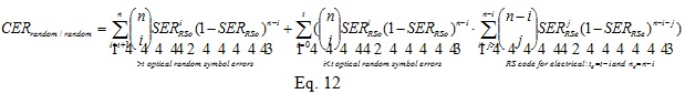

Table 4 lists the target DER0 and SNR that an electrical link would need to be to keep the optical link penalty as 0dB, 0.1dB, 0.2dB and 0.7dB. We can see that if the optical sub-link cannot take a large penalty (or in another words, to offer more FEC capability to electrical sub-links), the DER0 and SNR requirements for electrical sub-link are significantly tightened. For 200/400 GbE systems where 4:1 bit multiplexing, 2:1 codeword interleaving and precoding are deployed, if optical sub-link can only take 0.1dB penalty, the electrical link DER0 target has to be lower than 2.1e-5 while it only needs 1.6e-4 if the FEC is dedicated for the electrical link only. In order to maintain the electrical sub-link DER0 target higher than 1e-4, about 0.7dB penalty has to be taken from optical sub-link which could be considered too much.

Advanced FEC
Previous sections only focused on a RS (544, 514, 15) code over GF(210) (also-known-as KP4 FEC) for 100 GbE and 200/400 GbE systems and potential coding schemes like 4:1 bit multiplexing and 2:1 codeword interleaving. We can see that for severe error propagation cases or multi-part links, the KP4 FEC might not be able to relax DER0 to values SerDes designers require or provide the SNR coding gain that system designers want.
On the other hand, the KP4 FEC has about 100-200ns latency added to the system data path. For some low latency demanding applications, an alternative FEC that requires shorter encoding and decoding time is more attractive. In this section, we’ll explore other options including different coding schemes and even different FEC codes. For the exploration, three coding factors will be briefly discussed, coding gain, encoder/decoder latency and complexity. Note that this paper is more focused on performance analysis while the detailed study of implementation complexity and latency is beyond its scope.
Alternative coding schemes and RS codes
First let’s start with picking some low hanging fruit.
From section 3.1 we concluded that PMA bit multiplexing harms FEC performance. To make things worse, Ethernet systems with 100 Gb/s per lane interfaces are likely to increase the bit-multiplexing from 2:1 (deployed in the current 50 Gb/s interface) to 4:1. To avoid the bit multiplexing penalty we can consider symbol multiplexing described in Section 2. From Table 4 we can see that over 1dB (without precoding) and up to 0.4dB (with precoding) more coding gain can be achieved by replacing 4:1 bit multiplexing with symbol multiplexing. However, bit multiplexing is good-to-have for backward compatibility especially in chip to module interface. So symbol multiplexing coding schemes are more suitable for chip to chip or over backplane/cable interfaces.
The next low hanging fruit is to increase codeword interleaving depth. The current 50 Gb/s interface has an interleaving depth of 2. We can consider increasing it to 4, i.e. 4:1 codeword interleaving. By doing this, we expect the long burst errors will be further divided to 4 separate codewords. The analysis shows that up to 0.3-0.5dB coding gain can be achieved by increasing the codeword interleaving from 2:1 to 4:1 without precoding. However, the coding gain is reduced to negligible if precoding is deployed. Furthermore, decoding latency is proportionally increased by the interleaving depth unless striping over multiple lanes is implemented to reduce the latency with the cost of design complexity.
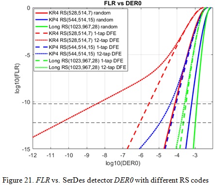
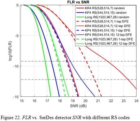
The 3rd low hanging fruit is to explore longer RS codes to improve the coding gain or shorter RS codes to reduce latency. For this paper, we studied two other RS codes besides KP4 RS (544, 514,15) code: KR4 RS (528,514,7) and Long RS (1023,967,28) both over GF(210). KR4 FEC has a lower overhead (or code rate) than KP4 FEC but with weaker error correction capability t=7. The Long RS code has a similar overhead as KP4 but longer codeword length (almost 2x) and therefore stronger error correction capability of t=28. We expect the KR4 code has slightly shorter encoding/decoding latency than KP4 but with a significant gate and area reduction compared with KP4 due to smaller t value, while the Long RS code has 2x encoding/decoding latency unless striping over multiple lanes is implemented.
Table 5 shows FEC performance with a coding scheme of 4:1 bit multiplexing and precoding to achieve 1e-18 post-FEC BER performance for the three RS codes and different error models. Figure 21 and 22 show the trending of FLR performance vs. SerDes detector DER0 and SNR requirements for the three RS codes. We can see that the stronger error correction capability the better long burst error tolerance, of course with the cost of encoder/decoder complexity and latency.

Advanced FEC options for next generation Ethernet
In this section, other FEC codes besides RS codes will be briefly discussed in terms of their coding gain, latency and complexity.
BCH codes are similar to Reed Solomon codes. BCH codes are a class of cyclic code [11]. The main difference is that the BCH code is over GF (2) thus it is a binary version of RS code for correcting multiple random errors. BCH codes are widely considered for applications demanding low latency since its codeword length in terms of bits is shorter than a similar RS code. However, BCH encoding and decoding complexity is nominally higher than RS codes since its computation is bit based instead of symbol based. Another disadvantage of BCH coding is its performance. It is fragile in burst channels with high DFE error propagation compared with RS codes.
To achieve complementary advantages between BCH and RS codes, we can combine those two in a concatenated code [11], a class of error correcting codes that consist of an inner code (BCH code) and an outer code (RS code). The outer code can be considered to use a KP4 type of RS code and the inner coder is a BCH code that could be short and only correct t=2 or 3 errors. By doing this, the complexity and latency is slightly higher than KP4 itself but with improved coding gain.
For an optical link that requires a high coding gain but less demands for low latency, a more advanced FEC like turbo product code, staircase code, or a low density parity checking (LDPC) code with iterative soft-decision decoding algorithm can be considered. Some of those codes can provide impressive coding gains and achieve channel capacity very close to the Shannon limit [11]. However, we believe their long latency (in the order of us or even ms) make them unsuitable for electrical links.
Conclusions
In this paper, high-speed serial link error propagation models and different Ethernet coding schemes have been studied and simulated to provide FEC performance analysis for 100/200/400 GbE systems with 100+ Gb/s per lane PAM4 interfaces. Different scenarios such as 1/ (1+D) mod4 precoding, PMA bit multiplexing, symbol multiplexing and FEC codeword interleaving and their impacts on overall system performance have been discussed. Multi-part link where a single FEC is shared between electrical and optical parts has been briefly studied as well. Advanced FEC schemes beyond current KP4 code are further explored.
An earlier version of this paper won the DesignCon Best Paper Award 2019.
Acknowledgement
I would like to thank my Broadcom colleagues Adam Healey and Shaohua Yang who helped me with FEC modeling and analysis through many fruitful discussions and feedbacks I also want to thank Pete Anslow from Ciena who had spent time and effort on the correlation between his results and ours for next generation 100G and 400 Gb/s Ethernet system.
Also See:
What is FEC, and How Do I Use It?, Signal Integrity Journal
Reference
[1]: IEEE Std 802.3bj-2014 IEEE Standard for Ethernet Amendment 2: Physical Layer Specifications and Management Parameters for 100 Gb/s Operation Over Backplanes and Copper Cables.
[2]: IEEE Std 802.3bs-2017 IEEE Standard for Ethernet Amendment 10: Media Access Control Parameters, Physical Layers and Management Parameters for 200 Gb/s and 400 Gb/s Operation
[3]: IEEE Std 802.3cd-2018 IEEE Standard for Ethernet Amendment 3:Media Access Control Parameters for 50 Gb/s and Physical Layers and Management Parameters for 50 Gb/s, 100 Gb/s, and 200 Gb/s Operation
[4]: IEEE 802.3 100 Gb/s, 200 Gb/s, and 400 Gb/s Electrical Interfaces Task Force: http://www.ieee802.org/3/ck/index.html
[5]: A. Healey and C. Liu, "Channel Operating Margin for 56 Gb/s PAM4 Chip-to-Chip and Backplane Interfaces," DesignCon 2016, Santa Clara, CA, 2016.
[6]: X. Dong, N. Huang and G. Zhang, “Improved Engineering Analysis in FEC System Gain for 56G PAM4 Applications”, DesignCon 2018, Santa Clara, CA, 2018.
[7]: Y. Lu, L. Ma, D. Mo and L. Liang, “High Gain Low Complexity Low Latency FEC Codes for Ethernet and Backplane Applications”, DesignCon 2018, Santa Clara, CA, 2018.
[8]: Gilbert, E. N. (1960), "Capacity of a burst-noise channel", Bell System Technical Journal, 39: 1253–1265, doi:10.1002/j.1538-7305.1960.tb03959.x.
[9]: Elliott, E. O. (1963), "Estimates of error rates for codes on burst-noise channels", Bell System Technical Journal, 42: 1977–1997, doi:10.1002/j.1538-7305.1963.tb00955.x.
[10]: P. Anslow, “BER and FER for 100GBASE-SR4”, 2012, Available online: http://www.ieee802.org/3/bm/public/mmfadhoc/meetings/nov29_12/anslow_01a_1112_mmf.pdf
[11]: S. Lin and D. Costello, Error Control Coding, Prentice Hall, February 2002.