
In October 2018, the world’s first electric vehicle (EV) equipped with remote wireless charging was rolled out in Germany, with plans for expanded release in the United States, the United Kingdom, Japan, and China.1 This EV represents decades of technological development towards plug-less EVs that many believe bring us one step closer to a future with dynamically self-charging autonomous vehicles.
Wireless technologies, including EVs with wireless power transfer (WPT), are proliferating rapidly: ABI Research predicts that the number of wirelessly chargeable devices will exceed 700 million by 2020. The number of EV models (both plug-in and wireless) is expected to grow, too, from 155 in 2017 to 289 by 20222, an expansion driven by stringent carbon emissions requirements and government-mandated initiatives worldwide.
One regularly cited inhibitor to even faster adoption is the need for a public charging infrastructure that is universally available. The technical teams behind these infrastructures are working diligently to both increase the number of currently available plug-in stations as well as drive technological innovation and drive down costs to deliver wireless charging infrastructures available in both public and private spaces.
This article examines several of the technical challenges that must be solved to bring this to fruition. First, let’s review the current state of WPT in general, and in automotive applications specifically.
Wireless Power Transfer
The mainstream WPT methods are electromagnetic induction and magnetic resonance. Both approaches realize contactless power transfer by using power-receiving coils to capture the magnetic field generated at the power transmission coils.
Common electromagnetic induction examples include electric shavers and cordless phones. While electromagnetic induction offers a simple principle and structure, plus low-cost system manufacturability, these systems are also prone to a drastic drop in power transmission efficiency as the distance increases between the power transmission and the receiving coils.3
On the other hand, magnetic resonance-based WPT transmits power via a capacitor in the power transmission and in the receiving sides to form LC resonance circuits, tuning both sides to resonate at the same frequency. This gives the systems an ability to maintain power feeds even with greater inter-coil distances, and/or when the centers of the coils are slightly shifted.3
Because magnetic resonance systems provide greater ranges of power transmission, and have demonstrated the potential for EV battery charging while in motion, this WPT technology has been in the spotlight in recent years as a solution for the automotive industry.
The automotive WPT applications currently consist of an external power pad that likely sits on top of the ground or may be embedded in the ground. The pad or plate has a circular coil that converts alternating electrical current into magnetic waves. A partner power amplifier controls this current and wave frequency. Inside the EV, a receiver located near the car’s power management system has a coil that’s tuned to receive magnetic waves at the same frequency as the source coil. The receiver converts the magnetic energy back into electric current to be stored in the car’s battery.
This approach relies on magnetic resonance because it loses little power (typically 7% to 10%) as it moves through the air, and is therefore considered to be highly efficient.4 WiTricity has commercialized a magnetic resonance WPT for automotive applications and TDK announced in early 2018 that it is working with WiTricity and automakers to develop a wireless charging system for electric vehicles, with an eye toward making easy, cable-free charging a commercial reality by 2021.5
The Need for Standards
The Society of Automotive Engineers (SAE) International has working groups around the world developing national standards on which automotive wireless charging systems can be based. The goal of the standards is to ensure that both private and public charging systems work with a myriad of different EV models.6
In November 2017, SAE International published its J2954 Recommended Practice (RP), the first industry-wide specification for WPT for EVs with motors of up to 11 kW power levels (WPT 3).7 The current version addresses unidirectional charging, from grid to vehicle, with the caveat that bidirectional energy transfer may be evaluated for a future standard.
As part of its specification, the RP provides a standardized test stand (first up to WPT 2 power levels) to give EV manufacturers and infrastructure companies the means for testing performance and validation of their products and new developments. According to the J2954 RP, the test stand is based on circular topology, but also provides a way to demonstrate compatibility to other topologies such as a “double D” design (See Figures 1 and 2).
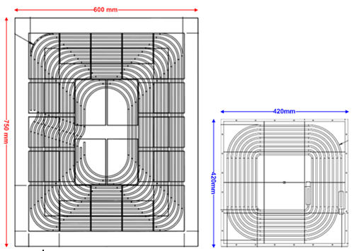
Figure 1. Circular WPT3 Ground Assembly and Vehicle Assembly.

Figure 2. DD Universal (WPT1-WPT3) Ground Assembly and Vehicle Assembly.
The J2954 states that WPT systems have two main components: a Ground Assembly (GA) unit and a Vehicle Assembly (VA) unit. The GA contains a grid-connected Power Factor Correction (PFC) converter, followed by a DC-AC inverter, a filter, and an impedance matching network (IMN) connected to a GA coil. The VA consists of a VA coil connected to an IMN and filter, a rectifier, and an optional impedance converter that produces suitable voltages and currents to the connected battery. During charging, the magnetic energy created by the GA coil is coupled to the VA coil.7
The adopted minimum common alignment method is executed by means of low power excitation (LPE). LPE is the method whereby the SAE J2954-compliant GA coil is excited at a low current to induce a detectable signal on the VA. The J2954 specifies a power-transfer-enabled vehicle ground clearance of up to 10 inches (250 mm), with a side-to-side tolerance of +/-4 inches (+/- 100 mm) and a front-to-back tolerance of +/-3 inches (+/-75 mm). This alignment assists drivers to stay within the charging range—and the future’s autonomous vehicles with finding parking spots—even in inclement weather conditions like rain or snow.
SAE International published a technical paper with bench test results from automobile and wireless charging suppliers measured at the U.S. Department of Energy (DOE) Idaho National Labs and TDK. The test report confirmed that WPT can be achieved at full power and with a high efficiency of up to 93% (grid to battery) with both matched and unmatched coil topologies, as well as charging between different power ranges (3.7 to 7.7 kW).7
In the months following the RP announcement, additional tests have been conducted—including in-vehicle field testing—for final validation. To date, 3.7, 7.7 and 11.1 kVA systems have been tested per the SAE standards, and 22 kVA units are under consideration. Very recently, 120 kVA systems have been demonstrated in a laboratory environment. Wireless power transfer rates have reached up to 90% percent efficiency compared to wired power transfers, even though the standards recommend a minimum 80% efficiency at offset positions of alignment.
Engineers developing optimal WPT especially in the public domain are grappling with the following questions:
- How much alignment must a car have with a wireless charging plate?
- How do materials like cement (in a garage floor) or asphalt (in a public space) affect the performance of a charging plate coil?
- How does the angle of the coil in an EV impact its charging capability when aligned with the charging plate coil?
- How will coils interact with one another in public spaces (e.g., where there are several parking spaces with chargers)?
Answers to these questions lie in the following aspects of automotive WPT. We’ll describe how each works, outline the current technical inhibitors, and present a snapshot of test data showing advancements toward overcoming the challenges.
Magnetic Resonance8
The magnetic resonance method of WPT helps overcome the problem of a drop in efficiency when the distance increases between the power transmission coil and the power reception coil. The extent of magnetic coupling between the transmission and the reception sides is expressed by a value known as the coupling coefficient or k. If the inductance of the power transmission coil and the power reception coil are L1 and L2 respectively, and the mutual inductance is M, the coupling coefficient k is expressed by the following formula:

 The coupling coefficient is a value in the range of 0≦k≦1, and it is ideally equal to 1 (=100% transmission efficiency) in the absence of leakage flux.7 In the magnetic resonance method, the capacitors are inserted on both the power transmission and the power reception sides to form an LC (inductor and capacitor) resonance circuit (see Figure 3). Power is transferred by matching the resonance frequency on both sides. Thus a high transmission efficiency can be obtained even when the coupling coefficient is low, typically <0.5.
The maximum transmission efficiency in the magnetic resonance method is expressed as a function of the product of the coupling coefficient (k) and the Quality factor (Q) of the coil (kQ product). Even if the coupling coefficient is low, high-transmission efficiency can be obtained by increasing the coil’s Q. However, several problems need to be overcome to implement the magnetic resonance method of WPT.
Inhibitors
The coil’s Q-value is expressed as Q=2πfL/R (where f is the resonance frequency, L is the coil inductance, and R is the coil’s AC resistance component). According to this formula, if inductance is increased by expanding the coil‘s diameter, or by increasing the number of turns of the coil, then theoretically, Q will be increased. However, since the resistance component also increases in this case, it is necessary to optimize the shape and the size of the coils during coil design in order to balance both.
Furthermore, in the magnetic resonance method, maximum transmission efficiency may be obtained when the power transmission and the power reception coils are placed at an optimum distance from each other. However, reducing this distance may cause the transmission efficiency to drop instead of increasing. This is due to deviations from the optimum distance when the mutual inductance M changes, causing the coupling coefficient and the resonance frequency to change. Additionally, the stray capacitance from the objects around the coils also affects the resonance frequency, resulting in an untuned, non-optimized system. Hence, a special circuit is typically required to automatically track and tune the circuit for the maximum efficiency. There are various techniques to compensate for these fluctuations in the resonance frequency, but this is the most important technical consideration in the magnetic resonance method, along with the coil design technology.
Simulated and measured data cannot be provided, but the typical resonant frequency of the WPT system is 81.38 – 90 kHz. The EMF fields are governed by International Commission on Non-Ionizing Radiation Protection (ICNIRP) 2010 standards. Field strengths vary depending on the regions specified for WPT systems. In the driver area and around the vehicle it is restricted to 21.2 micro-tesla. The field strengths are governed by the ICNIRP 2010 standards. Figures 4 and 5 show the nominal frequency sample azimuth measurements with sample spectrum analyzer and EMI measurements shown in Tables 1 and 2.

Figure 4. Coils Matched [0,0] Aligned, Nominal Frequency Sample Azimuth Measurements.
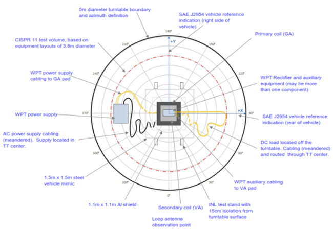
Figure 5. Test Setup Top View.6
|
EMI (dBµA/m) |
Angle (°) |
|
|
Max Hx: |
43.94 |
306 |
|
Max Hy: |
36.51 |
36 |
|
Max Hz: |
32.56 |
298 |
|
Detector |
Hx Trace (dBµV) |
CFrc (dB) |
Hx EMI (dBµA/m) |
|
Pk |
53.40 |
-10.17 |
43.23 |
|
QP |
53.00 |
-10.17 |
42.83 |
|
Avg |
53.30 |
-10.17 |
43.13 |
|
Detector |
Hy Trace (dBµV) |
CFrc (dB) |
Hy EMI (dBµA/m) |
|
Pk |
46.80 |
-10.16 |
36.64 |
|
QP |
46.30 |
-10.16 |
36.14 |
|
Avg |
46.60 |
-10.16 |
36.44 |
|
Detector |
Hz Trace (dBµV) |
CFrc (dB) |
Hz EMI (dBµA/m) |
|
Pk |
43.00 |
-10.16 |
32.84 |
|
QP |
40.20 |
-10.16 |
30.04 |
|
Avg |
41.10 |
-10.16 |
30.94 |
Electromagnetic compatibility (EMC)
Electromagnetic compatibility (EMC) means that a device is compatible with (i.e., no interference is caused by) its electromagnetic (EM) environment, and it does not emit levels of EM energy that cause electromagnetic interference (EMI) in other devices in the vicinity. The EMC in the WPT world includes the compatibility of the electronics in a vehicle to be able to work properly in the presence of strong magnetic fields generated by the WPT systems. Furthermore, the potential for a negative effect, if any, of these signals on human beings in the vehicle is worth a mention here.
The increasingly advanced electronics that are being incorporated into EV-component-level systems will need to be designed with the EMC in mind to ensure the reliability and safe operation of the vehicle. Each system component needs to coexist in the EM environment introduced by the EV systems as a whole (see Figure 6). These electrical system components introduce radiated or conducted EM energy of their own. For example, an intentional radiator such as a WPT system transmitter (e.g., transmission coil) can generate a strong signal at a specific frequency of operation that may couple with other vehicle electronic systems such as navigational and communication systems, resulting in operational failures. These types of interferences are introduced via coupling through wiring harnesses or PCB traces. The EMC circuits, such as filters, are designed for each system component to mitigate any potential EMI. These circuits include capacitors, inductors, resistors, and combinations thereof. Other electronic components that will help mitigate such interferences are ferrite materials in the forms of beads, clamps, toroids, sheets, and specifically designed ferrite material for wiring applications.
A WPT system supplies power at a specific rate according to the position of the VA coil within the required range relative to the GA coil. The power transfer will cease in the event of any out-of-specification circumstance. Furthermore, the power transfer needs to meet the efficiency targets at the full specified rated power. The WPT mechanisms are composed of the following components:
- Ground Assembly Mechanism:
- High-frequency power inverter
- Filter
- Transmit coil
- Regulation control and communication
- Vehicle Assembly Mechanism:
- Receive coil
- Filter
- Rectifier
- Regulation control and communication
- Secondary Energy Storage Mechanism:
- Secondary energy storage system
- Battery management system components
- In-vehicle communication modules
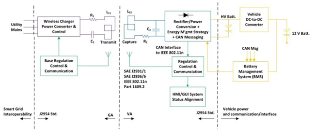
Figure 6. Block diagram of a single WPT charging station.
Conclusion
Many believe plug-less EVs will be a key to realizing a future with ubiquitous self-charging autonomous vehicles. For mass adoption to occur, there needs to be an accompanying public charging infrastructure that is universally available. Global industry leaders including TDK are working to define a clear set of WPT standards, including those governing EMC. Engineers developing optimal WPT for public spaces are grappling with issues such as the necessary degree of alignment precision between the charging plate and the EV, the effects of materials on EMC, the optimum coil angles, and the consequences of interaction among multiple coils in proximity together in public spaces. They are considering what effect EM signals may have on human beings in and around the wireless EVs. Pursuing ongoing research, development and testing of new methods, materials and designs, engineers around the globe are racing to solve the complex issues of WPT for the automotive industry.
Summary of Automotive WPT Pros and Cons:
Pros:
- Convenience: There is no need for manual charging, or connecting/disconnecting cables.
- Lower lifetime costs: There are fewer mechanical parts with the potential to break down and require repairs/replacement. There is reduced potential for rust or corrosion due to weather on cables or receptacle.
- Safety: There are no exposed high voltage or power outlets.
- Automatic: Autonomous vehicles are self-charging.
Cons:
- Lower efficiency: Currently, WPT is lower efficiency than wired options.
- Longer charging: WPT currently requires longer charging times than wired options.
- High upfront or setup costs: There are costs for updating the power infrastructure as mentioned above, installation of ground assemblies, etc.
- Susceptibility to weather: Extreme weather conditions could affect charge efficiency and/or the general ability to charge.
References:
- Is Wireless Charging for Cars Finally Here?, by Nathan Hurst, Smithsonian.com, 10-22-18
- Bloomberg New Energy Finance report on Electric Vehicles (2018)
- https://product.tdk.com/info/en/products/wireless-charge/technote/tpo/index.html
- The Little Company that’s Bringing Wireless Charging to Electric Cars, by Mark Sullivan, Fast Company, 02-27-18
- TDK to develop wireless charging system for electric vehicles, Nikkei Asian Review, 11-23-18
-
SAE standard J2954
- Schneider, J., Kamichi, K., Mikat, D., Sutton, R. et al., “Bench Testing Validation of Wireless Power Transfer up to 7.7kW Based on SAE J2954,” SAE 2017-01-2448
- SAE J2954 Recommended Practice
- SAE International Publishes J2954 Recommended practice Enabling Wireless Charging to 11kW, press release, 11-29-17
- https://product.tdk.com/info/en/techlibrary/developing/wireless/index.html