
It has been known for quite some time [1] that when we measure low impedance with the two-port shunt-through configuration, we potentially create an error due to the resistance of cable braids. This error, illustrated in Figure 1 (reproduced from [2]), can be reduced or eliminated in a number of ways, among others by using measuring instruments with floating or semi-floating [3] connector references or with appropriate preamplifiers.
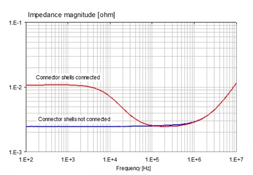
Figure 1. Illustration of the cable braid error when measuring a 2.5 mOhm resistor with semi-floating connections. Red trace: all connectors grounded. Blue trace: connector shells are semi-floating.
But what is the true nature of this error and what features of a preamplifier can help us to eliminate it? This is what we look at in this article.
Figure 2 shows the equivalent circuit of a two-port shunt-through measurement connection. You can easily see what creates the error shown in Figure 1 if you follow the current in the simplified equivalent circuit. The source is practically shorted, driving its shunt current through the Port 1 cable. This current goes through the DUT and has to return to the vector network analyzer (VNA) on the cable braids, which will lift the potential of the DUT_return point. If you then follow the path highlighted by the red line, you can also see a direct connection from the DUT_return point to the Port 2 input.

Figure 2. Two-port shunt-through impedance measurement scheme with a two-port vector network analyzer. Full and simplified equivalent circuits on the left and right, respectively.
Our problem is that while we want to measure the differential voltage across the unknown Zdut impedance, Port2 receives this voltage riding on a common-mode error voltage on the DUT_return point, and our typical VNA inputs have no common-mode rejection. This tells us that to reduce or eliminate this error, we have to either reduce the common-mode error voltage by limiting the current flowing in the cable braids, or we have to sense the voltage across Zdut in a differential fashion, or some combination of these two. All methods that address this problem are various implementations of these options. Using preamplifiers is one possibility, but the actual characteristics of the preamplifier still matter. Some preamplifiers work well on the Port 1 cable, some others work well on the Port 2 cable, yet some others will work equally well on both cables. Figure 3 shows these two options: preamplifier in series of the Port 1 or the Port 2 cable.
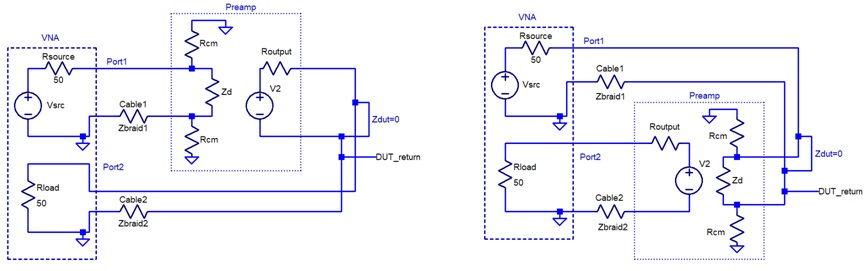
Figure 3. Preamplifier connection options: placing it on the Port 1 cable (on the left) or on the Port 2 cable (on the right).
We could certainly add preamplifiers in series to both cables, but it would be an overkill, and, as we will see below, if we are not careful how we choose the preamplifier features, two incorrectly selected preamplifiers actually may help less than one preamplifier with the correct features.
In Figure 3 the preamplifier is represented with a very simplified equivalent circuit. For now, we ignore its power supply requirements and don’t consider any frequency dependency either. There are five elements in the equivalent circuit: three resistors representing the common-mode and differential-mode input resistance, a voltage source, and a series resistor representing the output. For the purposes of this discussion, the voltage gain or the output resistance do not matter much. A unity-gain amplifier with 50-ohm output impedance is a good start, but different values could equally work. The two parameters that really matter are the input impedance and common-mode rejection of the preamplifier. As we explain below, whether we want to use the preamplifier on the Port 1 or Port 2 cable, different requirements will apply.
When the preamplifier is on the Port 1 cable, we can eliminate the cable-braid error with high input impedance. A high input impedance will significantly reduce the return current on the cable braid, and even if there is no common-mode rejection in the amplifier, the error is eliminated. On the other hand, when we chose to put the preamplifier on the Port 2 cable, input impedance does not matter, since the amplifier input is driven by the low-impedance DUT. However, in this case, the common-mode rejection becomes important: with the full shunt current of the source returning on the cable braid, we can suppress the error only if the preamplifier ignores the common-mode voltage on the DUT_return node and responds only to the differential voltage across the DUT. If we want a preamplifier to be effective on either the Port 1 or Port 2 cable, we need an amplifier with high input impedance AND high common-mode rejection.
Dependent on the application, there is a long list of further practical considerations. The cable braid error usually diminishes above a few hundred kilohertz, so luckily the common-mode rejection performance of the amplifier does not need to be very wide band. However, the common-mode input and output voltage ranges may become the limitation when we measure DUTs with DC bias voltage coming from the VNA or when the DUT itself is active, having its own DC source voltage: this can happen if we measure a power converter.
Also, when we have the preamplifier on the Port 1 cable, a high common-mode rejection (something that in this case we don’t need to reduce the cable braid error) would eliminate the possibility of measuring a capacitor with DC bias voltage coming from the VNA port. The output in this case may be stressed when we measure a live DC source: battery or voltage regulator. When we put the preamplifier on the Port 2 cable, the good common-mode rejection and high common-mode input voltage range become important so that we can measure active DUTs and components with DC bias. The power supply for the preamplifier is equally important. If we want the ultimate isolation, battery-powered preamplifiers are the best.
Build your own preamplifier?
There are professional preamplifiers on the market [4], which do a great job reducing the cable braid error. If you want to experiment with your own circuit, the rest of this article will help you. For the examples shown here, we use the robust AD815 dual operational amplifier. It has a guaranteed output current of 0.4A, 120 MHz closed-loop bandwidth and a 5 uA worst-case input bias current. With this operational amplifier we can build preamplifiers with very good performance up to at least 10 MHz.
Preamplifier with high input impedance
A preamplifier with a single package of AD815 is shown in Figure 4. The amplifier has 200 kOhm differential input resistance, but practically no common-mode rejection. It has a forward gain of -6dB between 50-ohm terminations and it can handle up to +- 2V DC bias on its input. Note that the input common-mode voltage range will increase if you use higher supply voltage. The schematic is shown in Figure 4.
The preamplifier was built up on perforated prototype board with no copper on either side. The power source was two sets of AAA batteries supplying +-6V nominal voltage. This preamplifier is a good choice for Port 1 applications so that the braid current can be blocked by its high input impedance. Because it has no common-mode rejection, this amplifier is not a good choice for Port 2 cables.
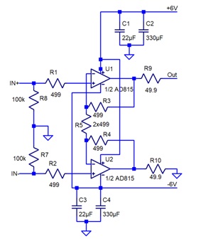
Figure 4. Schematic of preamplifier with high input impedance and no common-mode rejection.

Figure 5. Construction of the preamplifier with high input impedance and no common-mode rejection.
The construction is shown in Figure 5. There are right-angle SMA connectors on the input and output. For the sake of convenience, there are male and female connectors paralleled up on both sides; this will allow us to connect cables with SMA connectors without adaptors. The connectors, operational amplifier, bulk capacitors, and the power connector are on the top side. All other components are on the bottom side of the board. To protect the small components on the back from mechanical damage and to provide some insulation, the back side is covered with epoxy resin.
The preamplifier was measured in several different configurations. A typical test result is shown in Figure 6, taken with a Keysight E5061B VNA in the 1 kHz – 100 MHz frequency range.
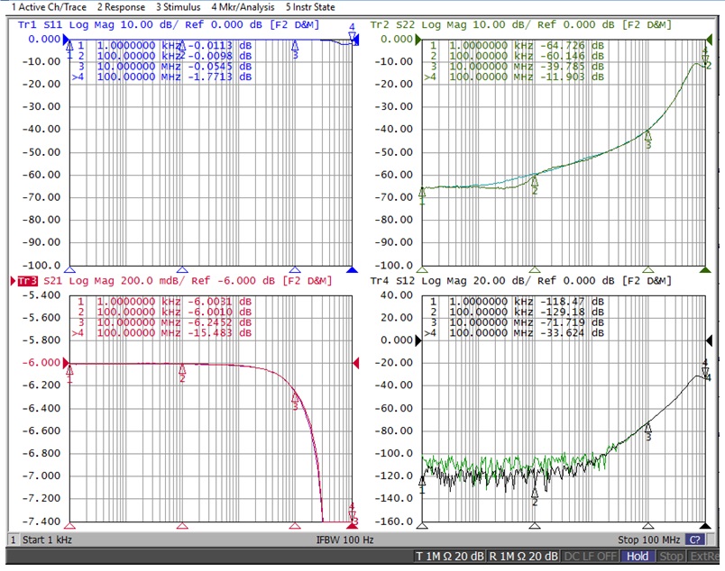
Figure 6. S parameters of the preamplifier shown in Figure 4 and 5.
Note that S11 magnitude is practically one because of the high input impedance. The output impedance is fairly well matched up to 10 MHz. Similarly, the forward and reverse transfer parameters, S21 and S12, behave well up to at least 10 MHz.
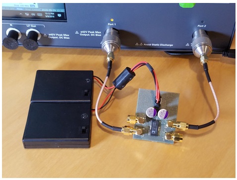
Figure 7. Setup for measuring the preamplifier.
The measurement setup is shown in Figure 7. Full two-port calibration was done on the network analyzer together with the coaxial cables. The RF power and the DC bias voltage on Port 1 were varied to find the compression points.