
Error Characteristics at Receiver Output
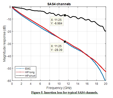
In this section, we examine the errors at the receiver output for data sent over the EMC long channel shown in Figure 1. In particular, we look at the distribution of the length of bursts of consecutive bits in error and the number of 5-bit symbols in error per FEC codeword.
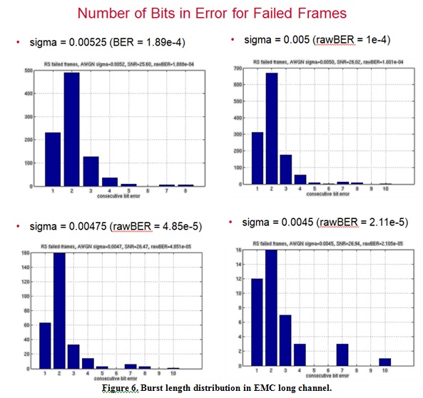
Burst length distribution:
Figure 6 shows the burst length distributions at selected AWGN noise amplitudes. The longest burst observed was 10 consecutive bits in error, which could impact 3 consecutive 5-bit symbols. For the cases with higher signal-to-noise ratio (SNR), it is very unlikely that two or more short independent error events would affect the same frame and overcome the error correcting capability of the FEC. In these cases, there is still a significant likelihood that a single burst of 7 or more bits in error affecting three symbols could defeat the FEC.
Raw symbol error distribution:
Figure 7 shows the distribution of symbols in error within the FEC frame. The symbol error distribution shows that the first and last symbols in each frame are more likely to be found in error than average. These locations are influenced by the header bits which take values of either 01 or 10. This observation can be explained by insertion loss related to the intrinsic Nyquist property of the 01 10 encoding overhead, and implied that using non-Nyquist patterns such as 128b/132b encoding (1100/0011) could be a better solution with slight increase on encoding overhead.

Study on Two-Way Three-Way Frame Interleaving
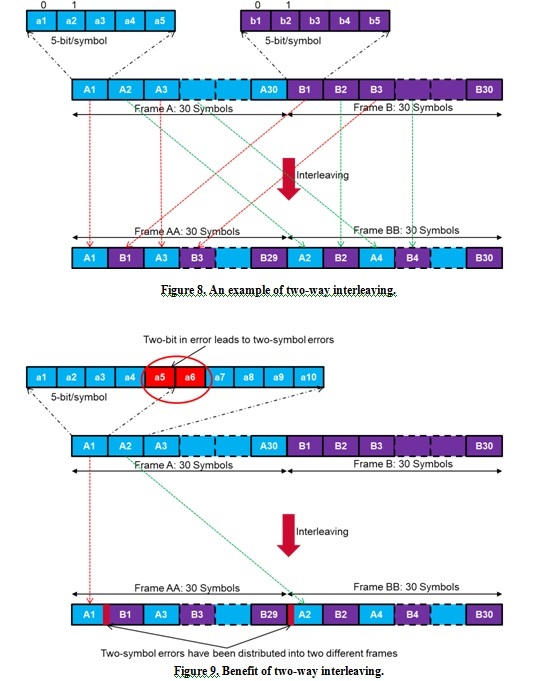
The most likely failure mode for the SAS 24G FEC with high insertion loss channels is a single burst of 7 or more consecutive bits in error leading to three symbols in error. Interleaving code words offers a means of breaking up this error pattern without increasing the error correcting capability of the FEC, which would introduce additional overhead.
Figure 8 gives an example of interleaving two 150-bit frames so that consecutive symbols in error will impact different FEC code words. Similarly by extending the two-way interleaving to three FEC codewords any three consecutive symbol errors will be distributed into three different FEC codes. Interleaving in this way significantly reduces the impact of burst errors on FEC performance.
Without doubt, interleaving will introduce extra delay. However, with the short FEC code length we use, the interleaving delay could be controlled in an acceptable range.
Simulation Results:
Figure 10 shows the simulation results of two-way and three-way frame interleaving in HP short channel. For HP short channel, 1e-6 raw BER can achieve 3e-14 after FEC BER. HP short channel has a very small H1 value, which leads to less error propagation, i.e., less burst errors. Therefore, the benefits of frame interleaving are not significant in this circumstance. As shown in Figure 9, two-way and three-way interleaving brings very little performance gain for HP short channel, and this observation meets our expectation.
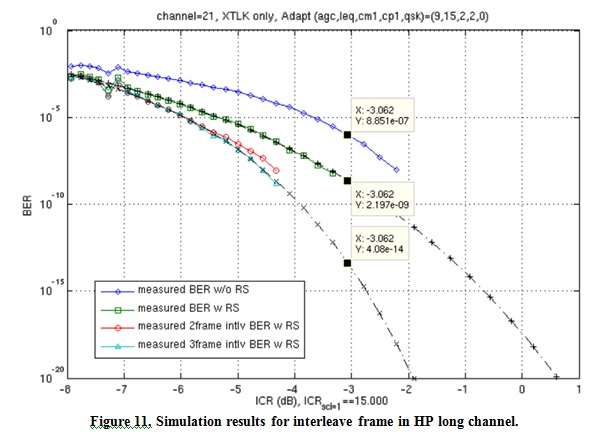
Figure 11 shows the simulation results of two-way and three-way frame interleaving in HP long channel. For HP long channel, 1e-6 raw BER can only achieve 2e-9 after FEC BER. HP long channel has a quite large H1 value, and it leads to more burst errors. As expected, two-way and three-way interleaving bring significant performance gain in our simulation results. By using two-way and three-way interleaving, 1e-6 raw BER can achieve 1e-14 region after FEC BER.

Study on RS Codes With Various Error Correcting Capability
To reduce introduced latency, we used a very short FEC code RS (30, 26). The disadvantage of the shorter FEC is that error correction is modest. The aim of our study is to find a good trade-off between code word length and error-correction capability of FEC for SAS4 channels.
Our study further compared the following three RS codes:
- Initial RS code with T=2, RS(30,26):
- 128/130 encoding (01,10)
- 5-bit per symbol, error correction capability T=2 symbols, code word length 150 bits
- code rate = 0.853, data rate 22.5GHz
- RS code with T=3, RS(50,44):
- 128/132 encoding (1100,0011)
- 6-bit per symbol, error correction capability T=3 symbols, code word length 300 bits
- code rate = 0.853, data rate 22.5GHz
- Need group two frames together to form an RS code word
- RS code with T=4, RS(52,44):
- 128/132 encoding (1100,0011)
- 6-bit per symbol, error correction capability T=4 symbols, code word length 312 bits
- code rate = 0.821, data rate 23.4GHz
- Need group two frames together to form an RS code word
As shown above, RS(30,26) and RS(50,44) have the same code rate, and the simulations use data rate 22.5GHz. However, RS(52,44) has a lower code rate, so its simulations use data rate 23.4GHz to compensate the code rate loss for a fair comparison.
Simulation Conditions:
For all the three RS codes above, we ran simulations with AWGN only and with AWGN/jitter/crosstalk combined noise for various SAS4 channels. All simulations have the following common conditions:
- Initial simulation settings are optimized for the specific channels;
- All adaptation loops are turned on;
- AC coupling 3dB corner is 0.3MHz;
- For simulations with AWGN/jitter/crosstalk (AWGN+Jit+Xtlk) combined noise, the static/random jitter noise and crosstalk noise are with fixed amount, and only AWGN sigma is changing.
Simulation Results:
We have shown in Figure 2 that RS(30,26) code is not strong enough to handle EMC long channel. RS codes with better error-correction capability are needed for SAS4 channel in order to meet raw BER = 1e-6 to after FEC BER = 1e-15.
Figure 12 and Figure 13 show the simulation results of RS(50,44) in EMC long channel with different noise properties. Figure 11 is for EMC long channel with AWGN only, where 1e-6 raw BER can achieve 5e-12 after FEC BER. Figure 12 is for EMC long channel with AWGN+Jit+Xtlk combined noise, where 1e-6 raw BER can achieve 1e-11 after FEC BER.