
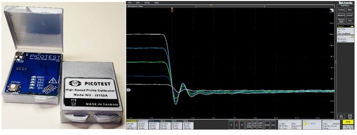
I recently designed an ultra-high speed, low-impedance pulse generator (Figure 1). I wanted it for evaluating oscilloscope probe performance [1], [2] and for determining the feasibility of an in-socket load for ASIC emulation. The obvious choice, due to size and desired performance, was an eGaN FET. One of the devices I used is an EPC2037, 0.9 mm device. As it turns out, the hard part wasn’t designing the pulser, but determining just how fast the pulse is and whether the pulse itself introduces ringing. In case I didn’t mention it, the eGaN device is also a flip chip, so there is no access to the device solder bumps once it’s installed.
The concept was simple enough: use the pulser to evaluate the bandwidth and ringing of a scope probe, and then measure the actual edge-speed and flatness of the pulse. In reality, it proved to be much more difficult.
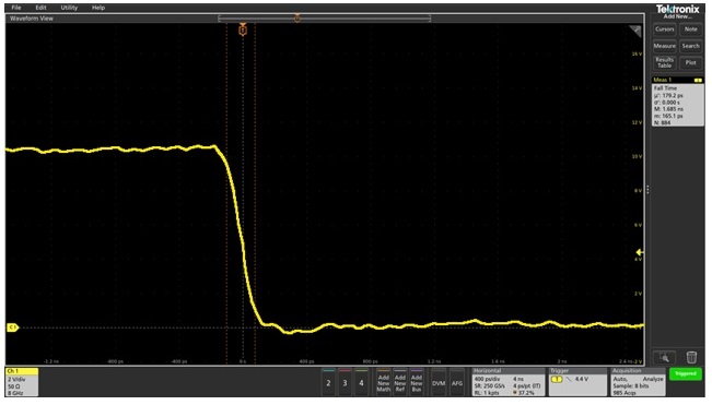
My first effort was to use the “best-in-class” Tektronix, P6150, 500Ω, 9 GHz passive probe. I had to slightly modify the pulse generator pull up circuit to drive the low impedance probe. The resulting edge speed, accounting for the 8 GHz oscilloscope (43ps rise/fall time) and the 9 GHz probe speed (39ps rise/fall time), is 169ps (Figure 2). That’s a great result, but is it right, or is it further limited by the tip leads of the probe? And did the pull-up modification also impact the result?
Following my own rule of measuring something you know, using the same measurement setup, before measuring something you don’t know, I measured a known signal. I measured the fall time of one of the clock buffers on the Picotest VRTS3 demo board.
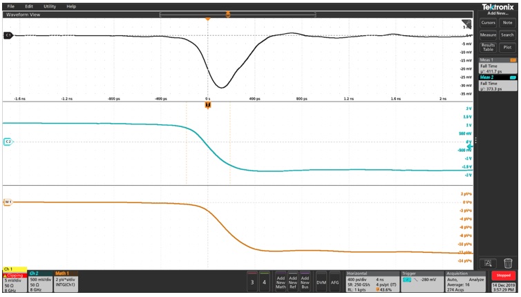
The direct measurement of the fall time, shown in Figure 4 is 373ps, while the “air-probe,” measured using the integration math function indicates 411ps. That’s within about 10 percent, and also on the conservative side.
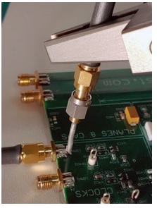
Moving on to our desired measurement, the probe was placed directly over the center of the GaN FET and the dV/dt was detected from the “air-probe.” Integrating the dV/dt results in a picture of the time domain response. The oscilloscope fall time can then be displayed using the built-in 90%/10% fall time measurement function within the oscilloscope. The response shows a relatively flat response, 138.9ps fall time (Figure 5).

Since we measured the “known” within 10% accuracy, it might be reasonable to assume this 139ps measurement to be valid. For validation purposes, we asked Langer EMV, a company that specializes in this near field extracted measurement, to use their own equipment to validate our measurement.
Using their MFA series probe and bias adapter, they measured the current fall time on a 6GHz Lecroy oscilloscope. Using an H field probe, they measured current fall time of 171ps, after correcting for the probe and scope bandwidth. Measuring the voltage fall time using an XF-E 10 E field probe, Langer measured 136ps, which is very close to our voltage fall time measurement (Figure 6).

Having our probe measurement validated by Langer EMV provides confidence that this 139ps fall time is correct, and this is likely the fastest GaN power FET ever recorded. This also validates my 2015 paper suggesting that this would likely be the best method of measuring ever faster GaN switching devices.
The MFA probe is a more precise, and amplitude-calibrated, probe compared against my “air-probe,” though both probes agreed on the fall time within 1.5% accuracy.
I want to personally thank Susanne Kaule and Philipp Günther from Langer EMV for performing this measurement.
References:
- Measuring a Scope Probe Requires Two Oscilloscope Channels and a Very Flat Signal Source, Steve Sandler, June 25, 2019. https://www.signalintegrityjournal.com/blogs/8-for-good-measure/post/1288-measuring-a-scope-probe-requires-two-oscilloscope-channels-and-a-very-flat-signal-source
- Measuring Oscilloscope Voltage Probe Performance, DesignCon 2020. https://www.dropbox.com/s/8jcrcr5pntwhol5/Paper_Track12_MeasuringoscilloscopeVoltageProbePerformance_Sandler_R1.pdf?dl=0
- Faster-Switching GaN : Presenting a number of interesting measurement challenges, Steve Sandler. IEEE Xplore, Volume: 2 , Issue: 2 , June 2015. https://ieeexplore.ieee.org/document/7130770