
Recently, IEEE 802.3 has established 200 Gbps, 400 Gbps, 800 Gbps, and 1.6 Tbps Ethernet task force which is aiming at 200 Gbps per lane link rate. In order to study what is needed and has been adopted for the next speed node, this article covers new forward error correction (FEC) technology, modeling, and performance analysis to aim at 200+ Gbps Ethernet systems and how different FEC options affect signal integrity (SI).
With the fast growth of 5G/6G networks and AI/ML applications, the serial link data rates continuously increase due to high-speed communications and large bandwidth demands. Recently, IEEE 802.3 has established a 200 Gbps, 400 Gbps, 800 Gbps, and 1.6 Tbps Ethernet task force 802.3dj4.The new task force is aiming at 200 Gbps per lane link rate, doubled from 100 Gbps per lane as in IEEE 802.3bs1 and 802.3ck2.
A decade ago, industry successfully updated the signaling format from NRZ to PAM4 during the transition from 25 to 50 Gbps link rates. To offset the signal-to-noise ratio (SNR) penalty caused by higher modulation levels, FEC has become an essential part of the solution for PAM4 systems. This article is subsequent to two previous articles, “What is FEC and How Do I Use It?”5 and “100+ Gbps Ethernet Forward Error Correction (FEC) Analysis)”6, and provides updates for the next generation Ethernet rate, 200+ Gbps per lane.
To study what is needed and what has been adopted for the next speed node Ethernet, this article investigates different FEC schemes such as end-end, concatenated, and segmented FECs as well as their performance in different applications and the effect of different FEC schemes on SI.
Keeping up with the latest decision made within the IEEE 802.3dj task force for 800GBASE-R and 1.6TBASE-R, in which Hamming (128, 120) inner code has been adopted as a part of the FEC solution for 200 Gbps per lane IM-DD optics7, concatenated FEC modeling and performance analysis became important to a multiple-part link system including a physical medium dependent (PMD) optical channel and two or more Attachment Unit Interface (AUI) electrical channels.
Refreshed Channel Error Model and FEC Performance Analysis
In “100+ Gbp/s Ethernet Forward Error Correction (FEC) Analysis,”6 random and burst channel errors and FEC performance analysis models were introduced for the 100 Gbps Ethernet rate. In this article, identical or similar models are used to study the next generation of FEC performance. In this section, we will add some updates based on the latest developments of the 802.3df3 and 802.3dj4 task forces.
FEC Architecture and Performance for 8×100G PHYs
Recently, the 802.3df task force adopted new Ethernet physical coding sublayer (PCS) and physical medium attachment (PMA) for 800GE with 8×100G PHYs, as shown in Figure 1. It is based on two 400GE1 PCS FEC flows (flow-0 and flow-1) in parallel. In total, there are 32 flow lanes, each running at 25 Gbps. Specific flow lanes map to a given PMA output lane such that 4:1 bit multiplexing is conceptually the same as 400GE.

Figure 1. 800GE with 8×100G PHYs PCS transmitter flow.
800GE with 8×100G PHYs has two flows, each contains two Reed Solomon (RS) (544, 514, 15) codewords. To utilize more coding gain, the 802.3df task force has decided to allow each physical lane to access all four FEC codewords equally, which results in 4-way codeword interleaving rather than 2-way codeword interleaving as in 802.3bs1.
Figure 2 shows post-FEC FLR performances vs. slicer SNR values with 2-way and 4-way interleaving schemes, respectively. We can see that 4-way interleaving outperforms 2-way interleaving, especially for burst errors with α=0.75. Such analysis and contributions have helped the 802.3df task force adopt 4:1 bit multiplexing and 4-way codeword interleaving in its PCS/PMA specification.
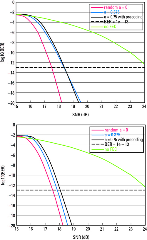
Figure 2. Post-FEC BER performance vs. slicer SNR values for 4:1 bit multiplexing with 2-way (top) and 4-way (bottom) codeword interleaving coding schemes.
200 Gbps FEC Schemes and Coding Algorithms for Optical Channels
The 802.3dj task force has doubled the data rate from 100 to 200 Gbps per lane. In this section, we will study the potential FEC solutions for chip to optical module interfaces at 200 Gbps data rate, provide performance analysis for different coding schemes and coding algorithms, and discuss their effects on system SI.
Three FEC Architectures
There are three major FEC architectures in a multi-part link system that have been discussed in the 802.3dj task force and shown in Figure 3:

Figure 3. Three types of FEC architectures (top: end-end; middle: concatenated; bottom: terminated).
- Type-1: Single FEC spans multiple AUIs and the PMD link, referred to as “end-end FEC”
- Type-2: Outer FEC spans multiple AUIs and PMD link (like Type-1) with an additional inner FEC spans PMD link, referred to as “concatenated FEC”
- Type-3: Different FECs are dedicated to AUIs and PMD links, referred to as “terminated FEC.”
200GBASE-R, 400GBASE-R, and 800GBASE-R with 100 Gbps per lane use Type-1 FEC, in which electrical AUIs and optical PMD link share a single FEC located at both ends of the hosts (such as switch chips). The performance analysis for such end-end FEC has been described in “100+ Gb/s Ethernet Forward Error Correction (FEC) Analysis”6. In order to meet the 1e-13 post-FEC BER target or the 6.2e-11 FLR target, the overall input BER to the end-end FEC needs to be 2.8e-4 or lower, with the combination of 2.4e-4 BER target for PMD link and 1e-5 BER target for AUI interfaces.
In order to double the data rate to 200+ Gbps per lane, the PMD link and/or AUIs might need extra FEC protection (further relaxing pre-FEC BER). Hence, both Type-2 and Type-3 FEC architectures are considered.
For Type-2 concatenated FEC, an outer FEC spans the whole link from host to host (like Type-1). An inner FEC spans only the PMD part. The inner FEC corrects most errors contributed by the PMD part, while the outer FEC corrects PMD errors not corrected by the inner FEC and errors contributed by the AUIs. The combined effect of inner and outer FECs results in the target BER and FLR for the whole link. This concatenated FEC scheme is new for 802.3.
For Type-3 segmented FEC, dedicated FECs protect different parts of the link such that DEC1 corrects errors contributed only by one chip-module interface, while DEC2 corrects error contributed only by PMD link. Since each part of the link has its own FEC protection, no BER target tradeoff between the AUIs and the PMD link is required. Both 400GBASE-ZR and 802.3cw use terminated FEC.
Compared to Type-1, both Type-2 and Type-3 might provide better coding gain to PMD link and/or AUIs. However, Type-3 FEC architecture expects extra latency, power, and complexity due to three FEC segments (three sets of encoders and decoders) to support. Type-2 FEC provides extra FEC protection for the PMD link with smaller increments in latency, power, and complexity compared to Type-3 FEC. The intent of Type-2 FEC is to provide a compromise which offers better performance than Type-1 and lower cost than Type-3. Therefore, Type-2 concatenated FEC has been adopted as a part of the FEC approach for 200 Gbps per lane IM-DD optics.7 Details of the proposed concatenated FEC will be discussed later. In next section, the outer FEC at the host sides will be studied.
Host FEC
Upon transitioning from 100 to 200 Gbps per lane, industry and the 802.3dj task force still prefer to keep the similar PCS structure and RS FEC for maximum reuse and backward compatibility.
Alternative Options of PCS Reed Solomon (RS) Codes
To ease the system design, certain construction rules and assumptions are taken for PCS RS code selection. For each candidate RS (n, k, t) over GF (2m)8:
- Each RS symbol consists of 8 to 12 bits (e.g., 10-bit symbol for KP-FEC, m=10)
- Assume 256B/257B block code to avoid additional transcoding
- Message size (m*k bits) corresponds to an integer number of 257-bit blocks
- Codeword spreads evenly across 4, 8, and 16 physical lanes
- Signaling rate is an integer multiple of a 625 MHz reference clock.
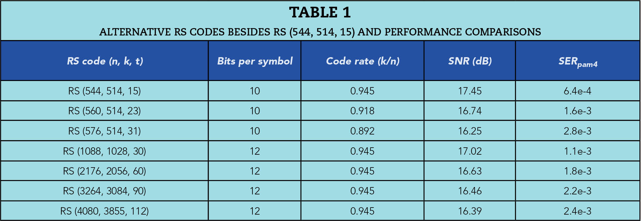
Table 1 lists a group of candidate RS codes that meet the above construction rules and assumptions. Their required slicer SNRs and SERpam4 to meet 1e-13 post-FEC BER are calculated for random error case (α=0, where “α” is the probability of getting an error in the next PAM4 symbol following an initial error). We can see that increasing error correction capacity t (number of RS symbol errors can be corrected per codeword) results in larger coding gain and relaxing pre-FEC BER target. For example, RS (576, 514, 31) and RS (4088, 3855, 112) codes can provide more than 1 dB coding gains over RS (544, 514, 15) code. However, the larger t value implies lower code rate and/or longer codeword length. Lowering code rate is undesirable for bandwidth limited copper channels such as backplane or copper cable channels. Meanwhile, the longer codeword length normally introduces larger latency and might not be suitable for systems with low latency requirement, such as AI and ML applications.
RS code encoder is a straightforward shift register8 which contributes negligible encoding latency while the majority of coding latency is from the decoder. An RS code decoder has three stages:
- Syndrome generation: FEC codeword accumulation time at port speed
- Key equation solver: Berlecamp-Massey algorithm normally has 2 t iterations plus a few additional clock cycles
- Chien search and data correction: FEC codeword size and datapath width dependent
Table 2 lists the decoder latency for different FEC codes with selected numbers of physical lanes and codeword interleaving depths. RS (544, 514, 15) FEC with 4-way codeword interleaving over 4×200G PHYs introduces ~55 ns latency.

It is likely that the 802.3dj task force will reuse RS (544, 514, 15) (also known as the KP-FEC) as PCS FEC code due to its backward compatibility and tradeoff between performance and latency.
Symbol Multiplexing and 4-way Codeword Interleaving Scheme
Analysis in “100+ Gb/s Ethernet Forward Error Correction (FEC) Analysis”6 showed that 4:1 bit multiplexing has larger coding gain penalty for burst errors than 2:1 bit multiplexing and symbol multiplexing. We can expect that increasing the bit multiplexing to 8:1 for 200 Gbps per lane will further degrade the performance.
To avoid bit-multiplexing penalty, symbol multiplexing is considered. It is not surprising to see in Figure 4 that SM+CI4 outperforms BM4 and BM8 for burst error case α=0.75 and reduces the gap to random error case α=0.
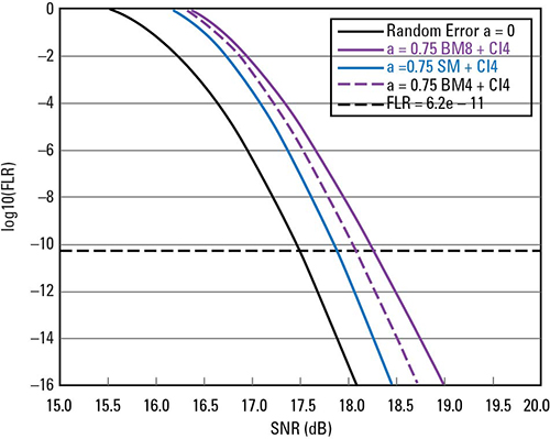
Figure 4. FEC performance for random error a=0 and burst error a=0.75 with 4-way codeword interleaving.
It is likely that the 802.3dj task force will adopt RS (544, 514, 15) with symbol multiplexing and 4-way codeword interleaving as its host PCS and PMA coding scheme.
Concatenated FEC: Inner Code and Decoding Algorithms for the Optical PMD
In this section, we will focus on Type-2 concatenated FEC, which has been adopted by 802.3dj as a part of the FEC approach for 200 Gbps per lane IM-DD optics.7
Hamming Code and its Encoder
For a concatenated FEC, the inner code should be short and with small overhead, such that the overall concatenated FEC has reasonable code rate and relatively low latency. Hence, Hamming codes or BCH codes8 have been considered.
Recently, the 802.3dj task force adopted Hamming (n=128, k=120) code as its inner code of the concatenated FEC. This inner code is based on the Hamming code (127, 120) by adding one extended parity check bit.
Due to the extended parity check bit, the minimum distance dmin=4. It will improve the error detection capability to 3 bits per codeword while the error correction capability is still 1 bit per codeword.
The encoding process of a linear block code or a Hamming code can be defined as a matrix operation: c=u .Gk,n, where c is the codeword sequence, u is the information part of the codeword, and G is the generator matrix that uniquely defines the linear block code.
Hamming Code Decoder
The decoding procedure for a Hamming code consists of three steps:
- Compute the syndrome sequence s of the received vector r to detect errors
- Identify the location of the error
- Correct the error.
In the first step, the syndrome sequence s is calculated as: s = Hn-k,n . r
where r is received noisy sequence and H is the parity check matrix paired with the generator matrix G.
If syndrome sequence s is all-zero, a correct transmission is assumed. Otherwise, errors are detected. For Hamming code (128, 120) with dmin = 4, it is able to detect up to three bits in error per codeword.
The second step of the decoding is generally the hardest part, to identify the error location. For a Hamming code with dmin = 4, it can only correct one bit error per codeword. Since there are eight bits in the syndrome sequence s = (s0, s1, s2, s3, s4, s5, s6, s7) and s0 is the extended parity bit, there are 27 possible patterns of s’ = (s1, s2, s3, s4, s5, s6, s7). For a hard decision decoding decoder, each of these s’ corresponds to a unique error location in r. After the error location is identified, the error can be corrected easily.
If there are more than 1 bit errors per codeword, such a decoding procedure could detect errors but miscorrect them in wrong locations, referred to as miscorrection. For concatenated codes, miscorrections are highly undesirable because they introduce additional errors (on top of channel errors) into the outer code decoding and sometimes make outer code decoder even harder to correct those miscorrections. For Hamming code (128, 120), the probability of miscorrection is as high as 0.5039 and not negligible. Figure 5 shows concatenated FEC performance with hard decision (HD) decoding for different channel error profiles, with DFE coefficients of h1=0 and h1=0.5. We can see that for random error case (h1=0), the inner code can improve slicer BER 1-2 order of magnitude and improve post-FEC BER 5-10 order of magnitude over KP-FEC only, equivalent to 1.5 dB coding gain to meet 1e-13 post-FEC BER. However, for correlated error case (h1=0.5), the performance of the concatenated FEC with HD inner code decoding degrades significantly due to the miscorrections. The coding gain reduces to only 0.3 dB.

Figure 5. Concatenated FEC performance with HD inner code decoding.
In order to mitigate the inner code miscorrection impact and improve the concatenated FEC performance, soft decision (SD) decoding algorithms and further interleaving schemes can be considered.
Soft Decision Decoding
If the outputs of the receiver are unquantized or quantized into more than two levels, a sequence of soft decision input can be taken to the decoder to process SD decoding.
Because the decoder uses the additional information to recover the transmitted codeword, SD decoding provides better FEC performance than hard decision decoding. In general, SD maximum likelihood decoding (MLD) of a code has about 3 dB of coding gain over HD decoding.8 However, MLD can be much harder to implement than HD decoding and requires more computational complexity and decoding latency.
To achieve a better trade-off between performance and decoding complexity, some practical suboptimal soft-decoding algorithms can be applied. Chase introduced three algorithms in “A Class of Algorithms for Decoding Block Codes with Channel Measurement Information”9, namely, algorithm-1, algorithm-2, and algorithm-3, with different levels of complexity. This article uses Chase’s algorithm-2 as the SD decoding algorithm for the inner Hamming decoder.
Let r = (r0, r1,…, r63) be a SD received sequence at the output of the receiver slicer. Each receiver symbol ri with 0 ≤ i ≤ 63, is decided independently to zi, zi ϵ {0, 1, 2, 3} for PAM4 signaling. Then, the magnitude of slicer error, |ri - zi|, can be used as a reliability measure of the HD decoded bit zi. The larger |ri - zi| is, the HD zi becomes less reliable. Based on the reliability measure of the received symbols, a group of least reliable positions (LRPs) can be identified. The precision of the slicer errors is implementation determined. 5-bit fixed-point values are used in this article for the slicer error, |ri - zi|.
In Chase’s algorithm-2, the number of LRP locations to consider is [dmin/2]. In our case, dmin=4 for Hamming code (128, 120). Hence, there are 22 possible test patterns, including the all-zero pattern. The decoding procedure is in following steps:
- Form the HD received sequence z from r and assign a reliability value to each symbol of z
- Generate the error patterns in E one at a time, possible in likelihood order. For each error pattern e in E, form the test patterns z+e
- Decode each test pattern into a codeword using HD decoder
- Compute the soft decision decoding metric for each generated candidate codeword
- Select the candidate codeword with the best metric as the coded solution.
There are different ways to compute SD decoding metric for each generated candidate codeword. As an example, we can add slicer errors of selected LRPs in each test pattern and corresponding HD corrected position. The larger the summation value, the more likely the generated codeword candidate is.
Figure 6 shows concatenated FEC performance with HD and SD inner code decodings for random error case h1=0. We can see that SD decoding outperforms HD decoding. SD decoding can improve slicer BER 2-3 order of magnitude and provide more than 2 dB coding gain to meet 1e-13 post-FEC BER compared with KP-FEC only.

Figure 6. Concatenated FEC performance with HD and SD inner code decodings for h1=0.
To improve the concatenated FEC performance, especially over burst channel errors, further interleaving schemes within PMD inner code sublayer are proposed.
Inner Code Interleaving Schemes
First, we can consider a block interleaver between PMD channel and inner Hamming code (128, 120). It simply arranges L Hamming inner codes into L rows of a rectangular block and then transmitting/receiving the block column by column. Even though the minimum distance of the interleaved block is still dmin=4 as an individual Hamming code (128, 120), this channel block interleaving can break a long burst PAM4 error into L different codewords.
By doing this, we expect that the concatenated code with channel block interleaving can tolerate longer burst errors or more DFE error propagation. Figure 7 shows the concatenated FEC performance with channel block interleaving of L=1, 2 ... and up to 8 for h1=0.5. We can see that with L > 4 the channel interleaving improves concatenated coding gain about 1.5 dB over KP-FEC only.
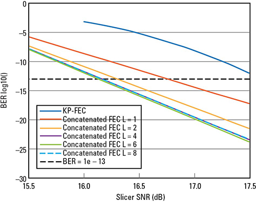
Figure 7. Concatenated FEC performance with channel block interleaving for h1=0.5.
To break the long burst errors and improve concatenated code performance, there are multiple interleaving schemes proposed in FEC baseline proposal for 200 Gbps per Lane IM-DD Optical PMDs7:
- Hamming interleaver L=8 to break the long burst errors into different inner codewords
- Circular shift block maximizes the distance in bauds between transmitted PAM4 symbols from two different RS symbols in the same RS(544, 514, 15) outer code
- Convolutional interleaver guarantees that the 12 x 10 bit payload of the Hamming encoder comes from 12 distinct RS codewords
The proposal FEC baseline proposal for 200 Gbps per Lane IM-DD Optical PMDs7 describes the above three interleaving functions. The proposal claims that the inner Hamming code (128, 120) with the above three interleaving functions could relax the PMD optical BER target from 2.4e-4 to 4.8e-3, more than one order of magnitude.
However, the major cost of adding inner code is the latency, especially with the convolutional interleaver. The latency of inner code itself, including encoder and decoding, is about 10 ns, while the convolutional interleaver for 800GBASE-R with 4-way RS codeword interleaving increases the latency to 56 ns. For 800GBASE-R/400GBASE-R with 2-way RS codeword interleaving, the latency could be further increased to 140 ns.
Low Latency PMD PHY
To cut the latency for a shorter distance of the PMD optical channel or better optic modules, two different FEC modes have been discussed and proposed to the 802.3dj task force:
- Mode_FECo: Optical link runs with RS (544, 514, 15) FEC protection alone, the same as end-end FEC
- Mode_FECi: Optical link runs with RS (544, 514, 15) FEC protection operating as an outer code, supplemented by Hamming code (128,120) protection operating as an inner code.
Of course, the PMD BER target would be different for these two FEC modes, provided that the error statistics are sufficiently random:
- Mode_FECo: The BER of the PMD link shall be less than 2.4e-4 when processed with an 800GBASE-R/1.6TBASE-R PCS
- Mode_FECi: The BER of the PMD link shall be less than 4.8e-3 when processed with an 800GBASE-R/1.6TBASE-R PCS and an inner code sublayer.
Basically, we need two separate PHY specifications. One is associated with Mode_FECi for optical channels longer than 2 km, and the other is associated with Mode_FECo for either short reach (say less than 500 m) or co-packaged optic (CPO) and linear pluggable optic (LPO) type of interfaces.
How Do FEC Options Affect System Signal Integrity?
From the discussions and analysis presented, we can conclude that different FEC options provide different coding gains with varying levels of cost, including coding overhead, coding latency, and complexity. Those factors will affect system signal integrity through different aspects.
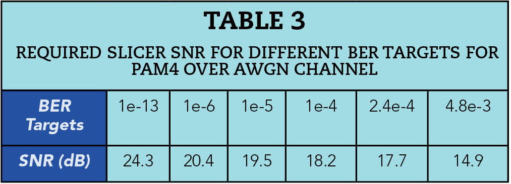
First, FEC can relax host SerDes BER target. The larger coding gain the FEC provides, the lower the BER target can be relaxed. For example, FEC baseline proposal for 200 Gbps per lane IM-DD Optical PMDs7 claims that the proposed concatenated code can relax PHY’s BER target from 2.4e-4 to 4.8e-3 for 200 Gbps. Table 3 lists the required slicer SNR for different BER targets for PAM4 signaling format over AWGN channel. Relaxing SerDes BER is equivalent to tolerating more noise, crosstalk, and jitter. Without increasing signal energy or equalization power, the proposed concatenated FEC can help us tolerate 2.8 dB more noise, jitter, crosstalk, or combined.
Second, strong interleaving schemes at host PCS or/and PMD inner code sublayers can effectively mitigate DFE error propagation, low frequency jitter, baseline wander, and other sources of correlated errors.
Of course, such high coding gain and long burst error tolerance of certain FEC options have inevitable cost. The proposed concatenated FEC provides up to 2.8 dB coding gain to the PMD link, but increases more than 6.7% link rate and more than 50 ns latency. The increased link rate could introduce significantly higher channel loss and crosstalk for a bandwidth limited channel. The increased latency could make the FEC option unsuitable to AI and ML applications in which a low latency requirement is critical.
Last but not least, the interoperability between different PHYs with different FEC options and FEC modes are desirable. The 802.3dj task force is developing the specifications to ensure such interoperability.
Conclusion
In this article, channel error models and FEC performance analysis have been updated according to industry changes. Different Ethernet coding schemes have been studied and simulated for 800GE and 1.6GE systems with 200 Gbps per lane. Concatenated FEC with soft-decision decoding for inner code to protect 200 Gbps optical link is investigated. The effect of different FEC options on system SI is discussed as well.
REFERENCES
- IEEE Std 802.3bs-2017 IEEE Standard for Ethernet: Media Access Control Parameters, Physical Layers and Management Parameters for 200 Gb/s and 400 Gb/s Operation.
- IEEE Std 802.3ck-2022 IEEE Standard for Ethernet: Physical Layer Specifications and Management Parameters for 100 Gb/s, 200 Gb/s, and 400 Gb/s Electrical Interfaces Based on 100 Gb/s Signaling.
- IEEE P802.3df 400 Gb/s and 800 Gb/s Ethernet Task Force, https://www.ieee802.org/3/df/index.html.
- IEEE P802.3dj 200 Gb/s, 400 Gb/s, 800 Gb/s, and 1.6 Tb/s Ethernet Task Force, https://www.ieee802.org/3/dj/index.html.
- C. Liu, “What is FEC, and How Do I Use It?” Signal Integrity Journal, https://www.signalintegrityjournal.com/articles/1284-what-is-fec-and-how-do-i-use-it.
- C. Liu, “100+ Gb/s Ethernet Forward Error Correction (FEC) Analysis,” DesignCon 2019.
- L. Patra, A. Farhood, R. Radhamohan, W. Bliss, S. Ramesh, and D. Cassan, “FEC Baseline Proposal for 200 Gbps per Lane IM-DD Optical PMDs,” IEEE P802.3dj Task Force, March 2023, https://www.ieee802.org/3/dj/public/23_03/patra_3dj_01b_2303.pdf.
- S. Lin and D. Costello, Error Control Coding, Prentice Hall, February 2002.
- D. Chase, “A Class of Algorithms for Decoding Block Codes with Channel Measurement Information”, IEEE Trans. on Information Theory, Vol. IT-18, No. 1, January 1972.