
Editor’s Note: A cable that leaks electromagnetic energy sounds like a defective cable. Yet, ironically, it makes an excellent broadband antenna. To avoid confusion, antennas based on this approach are called leaky feeders. They are typically used in environments that mirror the cylindrical shape and length of the cable: tunnels, mines, aircraft, railroad tracks and skyscrapers.
CST provides a tutorial explaining the basic theory and electromagnetic performance. Turning theory into practice, with assistance from W. L. Gore, we examine their use enabling Wi-Fi and cellular service on commercial airlines and corporate jets.
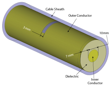
Figure 1 A simulation model of a coaxial cable with a single slot.
The leaky feeder antenna is an adaptation of the standard coaxial cable, with one key difference: the outer conductor is slotted or punctured, allowing the cable to radiate. Based on cables, leaky feeders are strong, flexible and robust against environmental conditions. Together, these characteristics make leaky feeders a good candidate for providing mobile connectivity and RF sensor coverage in confined, challenging environments such as tunnels, underground facilities, mines, factories, ships and aircraft.
The leaky feeder doubles as both a transmission line and an antenna. Waves propagate through the dielectric, with currents running along the inner and outer coaxial conductors. These waves can “leak” through gaps in the outer conductor. In a normal coaxial cable this is, of course, unintended behavior, however this is what allows the cable to act as an antenna.
A leaky feeder antenna is effectively an array, with numerous radiating slots along its length. There are several classes of leaky feeders, which depend on the shape of the slots. This explanation of the antenna characteristics will focus primarily on the simple case where the slots are rectangular, regular and run circumferentially perpendicular to the axis of the cable. The same principles apply to a wide range of leaky feeder antennas.
The first step in understanding how a leaky feeder antenna operates is to examine the behavior of a single slot (see Figure 1). Although radiation from leaky feeders is described in layperson’s terms as the fields “leaking” through the shield, there are really two distinct modes: radiated and coupled.
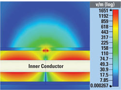
Figure 2 Simulated E field at 3 GHz, inside the cable and around a slot.
RADIATED MODE
In radiated mode, each slot behaves as a magnetic dipole antenna. The slot will interrupt the current lines running along the outer conductor of the coaxial cable, which causes the slot to radiate as simulated1 in Figure 2. The radiation pattern for the slot is directional, but the width of the main lobe is very large, as shown in Figures 3 and 4. This offers good coverage within the tightly enclosed spaces in which leaky feeders are used. For this simple slot design, the radiation efficiency increases with frequency, as the wavelength of the radiation becomes comparable with the length of the slot. More complex designs can be used to adjust the electrical size of the slot to tune its radiation properties more finely.2 Individually, a single slot is not a very effective radiator. By design, the slots are not usually resonant, which would improve the radiation.3
Analyzing the loss through the cable, Figure 5 shows the simulated S21 for a short section with a simple slot (Figure 1) is only -0.097 dB at 3 GHz. However, a 100 meter run of a leaky feeder may include thousands of slots, and the losses will quickly accumulate resulting in significant attenuation of the signal. In applications with long cable runs – a tunnel or mine, for example – booster amplifiers will be installed at regular intervals to compensate for the losses.
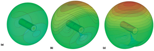
Figure 3 Simulated 3D far field radiation pattern for a single slot on a short length of cable at 1 GHz (a) 1.5 GHz (b) and 3 GHz (c).
As a compromise between maximizing antenna efficiency and minimizing coaxial mode attenuation, leaky feeders are often designed with leaky sections interspersed with shielded sections (see Figure 6). This also improves the directionality of the antenna by suppressing higher-order harmonics outside the cable, as shown in Figure 7.
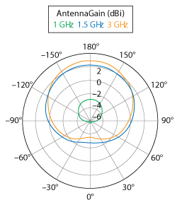
Figure 4 Simulated 2D far field radiation patterns vs. frequency (plane midway through the slot and perpendicular to the cable length).
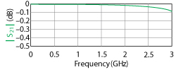
Figure 5 Loss vs. frequency for a short cable section with a single slot.
When multiple slots are combined, they behave as an array. This significantly affects the performance of the leaky feeder, compared to individual dipole slots. The phase difference between the slots, proportional to the distance between the slots relative to the wavelength in the dielectric, causes constructive and destructive interference. This interference results in beam steering, meaning the maximum gain is not normal to the cable; rather, it is directed at an angle that varies with frequency (see Figure 8).
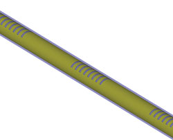
Figure 6 A length of leaky feeder with alternating leaky and shielded sections.
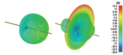
Figure 7 Comparison of the simulated radiation patterns for 2 m of continuously slotted cable (left) and periodically slotted cable (right) at 1.5 GHz.
The leaky feeder resembles a conventional slotted waveguide antenna with one key difference: in leaky feeder antennas, the n = 0 harmonic does not radiate. This means that it is not necessary to alternate the placement or alignment of the slots to cancel this harmonic.3
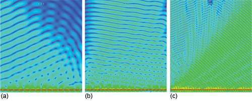
Figure 8 Simulated E field around a 2 m length of periodically slotted leaky feeder at 1 GHz (a) 1.5 GHz (b) and 3 GHz (c). The changes in beam orientation with frequency reflect the cumulative phase interference from the individual slots.
The leaky feeder is typically used in an enclosed space, such as a tunnel or aircraft fuselage. Since the frequency of operation is much greater than the cutoff frequency of the enclosure, propagation of the radiated mode through the enclosure is mainly by reflection. Figure 9 shows the propagation in a concrete tunnel, simulated with a ray-tracing asymptotic solver.1
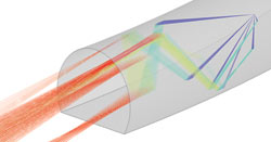
Figure 9 Simulated propagation from a short length of leaky feeder cable (not shown) in a concrete tunnel at 3 GHz. The colors distinguish the direct signal from the various reflections.
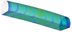
Figure 10 The simulated E field from a short section of leaky feeder cable (not shown) in a 5 m diameter concrete tunnel at 60 MHz. The tunnel acts as a waveguide.
COUPLED MODE
While radiated mode can operate in free space, coupled mode relies on the interaction between the cable and its environment – typically enclosures that act like waveguides. Consider a leaky feeder running through a tunnel. The outer conductor of the leaky feeder can be considered the inner conductor of a much larger coaxial cable, where the walls of the tunnel form the outer conductor (see Figure 10). The leaky feeder is a mode convertor between the coaxial mode (in which the coaxial cable is the waveguide) and the monofilar mode (in which the tunnel itself is the waveguide).2 Coupled mode dominates at low frequencies, where the wavelength is much greater than the slot spacing.5 In this mode, the antenna radiates at discontinuities, such as irregularities in the wall and interactions with the cable mounts. The radiation increases when the cable is close to the wall, where the interaction between the coaxial mode and the discontinuities is stronger.
The performance of the leaky feeder in a waveguide enclosure will also be improved by alternating leaky and shielded sections. Currents propagate along the outside shielded sections, allowing the cable to radiate without significant attenuation in these regions.2,5 Although the requirement for an outer wall restricts the use of coupled mode to specific applications, reducing attenuation allows the distance between amplifiers to be increased, which improves the performance of the leaky feeder.6
References
- Simulations were performed with the finite element model (FEM) solver CST STUDIO SUITE, www.cst.com. Full-length cables were simulated using a finite integration technique (FIT) solver according to IEC 61196-4, “Coaxial Communication Cables – Sectional Specification for Radiating Cables.”
- P.P. Delogne and L. Dryck, “Underground Use of a Coaxial Cable With Leaky Sections,” IEEE Transactions on Antennas and Propagation, Vol. AP-28, No. 6, pp. 875–883, November 1980.
- A.A. Oliner, D.R. Jackson, “Leaky Wave Antennas” in J.L. Volakis, Antenna Engineering Handbook Fourth Edition, pp. 11-1 – 11-56.
- J. H. Wang and K.K. Mei, “Theory and Analysis of Leaky Coaxial Cables with Periodic Slots,” IEEE Transactions on Antennas and Propagation, Vol. 49, No. 12, pp. 1723–1732, December 2001.
- M. Piette, S. Collin, R. VanThienen and P. Delogne, “Electromagnetic Field Produced by a Pair of Parallel Leaky Feeders in a Tunnel,” Proceedings of the Progress in Electromagnetic Research Symposium 2004, pp. 313–316.
- Eupen AG, “RF Cables for Radio Transmission in Confined Areas,” datasheet.
LEAKY FEEDERS ENABLE AIRLINE Wi-Fi
W. L. Gore and Associates (Gore)
Major airlines are offering Wi-Fi access to the Internet on many of their flights and moving quickly to deploy the service to virtually all aircraft. Some airlines outside the U.S. — Emirates, for example — also offer cellular connections, allowing passengers to text and make calls using their mobile phones. Within just a few years, Wi-Fi has moved from a unique feature to attract flyers, to a frustration when connections are slow or it is not offered on the flight. The growth in demand has service providers such as Global Eagle, Gogo and ViaSat upgrading their systems to increase data rates and provide global coverage.
If you fly frequently, none of this is news. What you may not know, though, is that leaky feeder antennas are an important part of the system.
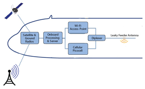
Figure 11 Simplified block diagram of system for providing inflight Wi-Fi and cellular service.
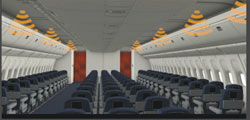
Figure 12 The leaky feeder antennas are mounted in the aircraft ceiling above the aisles.
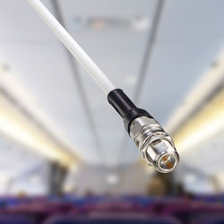
Figure 13 GORE Leaky Feeder Antennas look like a traditional RF cable.
Whether the aircraft is connected to the Internet with a radio link to the ground or to a satellite (and then back to earth), the onboard equipment is similar (see Figure 11). A Wi-Fi access point routes data back and forth between the passengers and an onboard processor, using a leaky feeder as the antenna. If the airline also offers cellular service, a separate picocell connects to the same leaky feeder antenna through a diplexer. The size of the aircraft determines the number of access points and picocells, which defines the number of leaky feeder runs in the cabin. For a wide-body aircraft like the Airbus 330 or Boeing 777, each aisle will have a leaky feeder, as illustrated in Figure 12.
While uniform RF coverage throughout the cabin is important to passengers, the leaky feeder must also be airworthy, meeting requirements for flame and smoke toxicity. The antenna must be strong mechanically to withstand vibration and abrasion, ensuring it does not fail during the lifetime of the aircraft.
W.L. Gore and Associates is the leading manufacturer of leaky feeder antennas for aircraft applications and one of few suppliers certified, according to Gore product specialist, Adrian Milne. He estimates that Gore’s antennas are flying on more than 1000 commercial aircraft, including Airbus and Boeing. Dassault Aviation selected their leaky feeders for the Falcon 7× corporate jet, as part of a system that provides cellular service during flight.
The frequency response of GORETM Leaky Feeder Antennas (see Figure 13) covers 400 MHz to 6 GHz, so a single antenna run handles all cellular and Wi-Fi bands. The antennas are manufactured in three diameters, from 6.5 to 11.7 mm, with the smaller diameter cable lighter and with a tighter bend radius. The trade-off with the smaller diameter is lower gain.
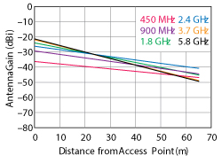
Figure 14 Antenna gain vs. frequency and distance from the access point.
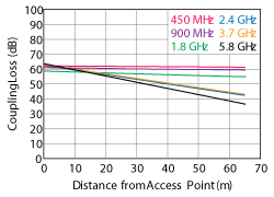
Figure 15 Antenna coupling loss vs. frequency and distance from the access point.
Figure 14 shows the measured gain of the smallest diameter leaky feeder as a function of frequency and distance from the access point. The measured coupling loss for the same antenna versus frequency and distance is plotted in Figure 15. For reference, the length of the cabin in an Airbus 330-300 is 50 m.
Both the antenna gain and coupling loss were measured according to the free space method specified by the International Electrotechnical Commission (IEC) in standard IEC-61196-4. The leaky feeder is elevated to
2 m above the ground, held by non-metallic posts, and the measurement antenna is positioned at the same height and 2 m from the leaky feeder. The data reflects only the radiated mode of the leaky feeder, not any interaction that the antenna would have with the metal fuselage of the aircraft.
Airline flights used to offer harried travelers a few hours of isolation and thoughtful reflection, disconnected from the world by the limitations of technology. No longer. The leaky feeder antenna is playing a part in the encroachment of 24/7 connectivity — even in the skies.