
Measuring small resistance values is not trivial, but since 1861, when Lord Kelvin invented the Kelvin bridge,1 we at least have a solution for measuring very low DC resistances: the four-wire Kelvin connection (see Figure 1). We measure the resistance by sending a known current through the resistor and measure the voltage drop using separate wires.

Figure 1. Sketch of the four-wire Kelvin connection.
To avoid the measurement error created by the voltage drop along the connection between our measuring instrument and the device under test (DUT), we separate the two loops. We use two wires to send a known I current through the unknown R resistor, and we use two separate wires to sense the V voltage. We will have voltage drop along the wires sending the test current. But this will not matter if we make sure that the two wires we use to sense the voltage across the unknown R resistor do connect to our resistor and do not include any piece of the wires that carry the test current. The voltage drop along the wires that connect to the voltage-measuring instrument can also be disregarded: the input resistance of today’s voltmeters is so high compared to the wire resistance (MOhms vs mOhms, at least a 109:1 ratio) that the attenuation can be ignored.
The medium-frequency equivalent for AC impedance measurements came along almost 130 years later. As it usually happens, the AC solution was inspired by pure necessity. In the Fall of 1997, a new mid-range server was on the drawing boards at SUN Microsystems and my task was to design the power distribution network for the CPU module. The CPU core rail voltage was nominally 1.8 V with a maximum current of 50 A. The allowed voltage fluctuation and assumed current transients required a 5 mOhm PDN impedance on the CPU board. This was the time when the target-impedance concept was already known,2 but a systematic validation process by measurement was still a challenge.
Impedance-measuring instruments were limited to a fraction of an Ohm as the lowest impedance they could reliably measure. After trying different vector network analyzers and other instruments in the usual 1-port reflection-based approach, it became clear that the major limitation was not only the instrument itself, but also the connection we have to use to our unknown impedance.
Mimicking the four-wire DC resistance measurement setup, the 2-port shunt-through measurement concept3 was a practical way out of the dilemma (see Figure 2). Port 1 of the network analyzer sends out a calibrated test signal, and we use the dedicated Port 2 connection to pick up the small voltage across the DUT. It works just like the four-wire Kelvin connection for DC resistance, but now we have the backing of a precision AC instrument, allowing us to extend the frequency range well into the GHz frequency range.

Figure 2. The 2-port shunt-through impedance measurement concept.
One notable difference is that, as opposed to the very high input resistance of DC voltmeters, vector network analyzers (VNA) today tend to have the standard 50Ω impedance. To avoid the error caused by the cable losses, we can make a calibration to the end of the cables. Low-impedance devices very seldom have dedicated coaxial connectors for impedance measurement purposes, so we have to make the final connection ourselves with custom probes or with short wires. Nevertheless, these last pieces will be outside the calibration loop. In Figure 2, they are called Zconnection. Since they are in series to the 50Ω cables, for all practical purposes below 1 MHz, they do not impose significant limitations.
The next major hurdle was the lack of accessories. RF and microwave measurements have a large range of standardized coaxial connections to choose from and then we de-embed the connector and fixture that leads up to the device we measure. For low-impedance power component measurements, this approach would impose too many limitations. It is more straightforward to use hand-soldered connections at low frequencies, or probes at higher frequencies.
Next, we need to take care of the cable-braid loop effect.4 It requires amplifiers or common-mode transformers tailored to the applications. In 1997, none of those were readily available, and the first 2-port shunt-through measurements were quite rudimentary by today’s standards.
To illustrate one of the extreme solutions, Figure 3 is a photo of a toroid transformer that I used for years to eliminate the cable-braid error. The 1:1 isolation was achieved with 2× 50 turns of AWG#20 wire. The wires of the primary and secondary were wound together in a bifilar fashion. Two SMA female connectors were soldered to the winding ends, making it easy to use the isolation transformer with SMA cables. It had a Phillips TX51/32/19-3F3 ferrite toroid core. The fact that the coils were insulated from each other guaranteed the good cable-braid error suppression, but when either side included an active source—for instance, during the measurement of live DC-DC converters—the current through the winding was actually limited by the connecting coaxial cables. Some of the cables got quite warm.
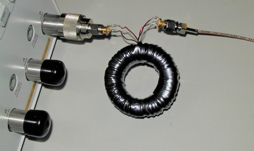
Figure 3. Toroid transformer to break the cable-braid loop.
Over the years, luckily, instruments with semi-floating ground5 and probes/accessories have become available.
Today, the 2-port shunt-through methodology is still very relevant. Our instruments are becoming more sensitive, but the target impedance keeps dropping as well. Some of the latest designs require 0.1 mOhm or less impedance on the supply rail, which is starting to stress the noise floor of the instruments.
We can boost the received signal in several ways. One option is to increase the drive strength, which in VNAs today is limited to about 20 dBm. Separate injectors6 or current boosters7 can be used on the driver side, and/or low-noise preamplifiers can be used on the receive side.8 For people who like tinkering with electronics, a set of amplifiers for different cases were described in.9
When we use two probes to connect to the DUT there is a practical limit to how close we can connect the probes without touching. With hand-held semirigid probes, the minimum spacing is approximately 20 mils, small enough that the spatial attenuation through the PCB structure should not matter. However, with higher currents and perforated planes under chips, even on a very small plane shape, we can end up with horizontal plane resistance, which is not negligible compared to the shunt impedance of capacitors. Suddenly, location matters, and the result depends on where we position the probes. Practical implications of this on DC-DC converter stability are described in.10
Finally, just a brief reminder. Correlation between simulations and measurements is important, but in simulations we are not limited by the practical side-effect that plague our measurements. Whether we do circuit simulations or field-solver simulations, in simulations the 2-port shunt-through connection is necessary only if we are studying the impact of connection details. The numerical accuracy of circuit simulators is high enough that we do not need a workaround.
References
1. “Four-Terminal Sensing,” Wikipedia, https://en.wikipedia.org/wiki/Four-terminal_sensing.
2. L. D. Smith, R. E. Anderson, D. W. Forehand, T. J. Pelc, and T. Roy, ‘‘Power Distribution System Design Methodology and Capacitor Selection for Modern CMOS Technology,’’ IEEE Transactions on Advanced Packaging, Vol. 22, No. 3, August 1999, pp. 284–291.
3. I. Novak, “Probes and Setup for Measuring Power-Plane Impedances with Vector-Network Analyzer,” DesignCon 1999.
4. I. Novak and J.R. Miller, “Frequency-Domain Characterization of Power Distribution Networks,” Artech House, 2007.
5. I. Novak, “Accuracy Improvements of PDN Impedance Measurements in the Low to Middle Frequency Range,” DesignCon 2010, February 2010, www.electrical-integrity.com.
6. “J2101A Injection Transformer 10Hz - 45MHz,” Picotest, www.picotest.com/products_J2101A.html.
7. E. Koether and I. Novak, “Transient Load Tester for Time Domain PDN Validation,” EDI CON USA 2017, www.electrical-integrity.com/Paper_download_files/EDICON2017-PAPER_TLT-TimeDomainValidation.pdf.
8. “J2180A Ultra Low Noise Preamps,” Picotest, www.picotest.com/products_J2180A.html.
9. I. Novak, “Preamplifier Options for Reducing Cable-Braid Loop Error,” Quietpower Columns, December 2018, www.electrical-integrity.com/Quietpower_files/QuietPower-48.pdf.
10. A. Miranda, J. Hartman, K.Narayandass, E. Koether, G. Blando, and I. Novak, “How Spatial Variation of Voltage Regulator Output Impedance Depends on Sense Point Location,” DesignCon 2018, www.electrical integrity.com/Paper_download_files/DC18_PAPER_Track11_HowSpatialVariationofVoltage_Miranda_updated__.pdf.
Article was published in the SIJ January 2020 Print Issue, Reflections: Page 16.