
A vector network analyzer (VNA) is an essential measurement tool for RF design and is often used to characterize the performance properties of filters, amplifiers, antennas, and the like. It might be surprising to learn that this versatile tool may also be used to measure and optimize the power supply systems which drive digital, analog, or RF circuits.
Possible power supply measurements include output impedance, output stability, power supply rejection ratio (PSRR), and reverse isolation. Each of these measurements are important to verify and optimize a design for best stability and noise performance. The ideal output impedance of a power supply such as a switching regulator or a low drop out (LDO) regulator is “flat” from very low frequencies to the highest frequency which is present in the circuit.
For digital circuits, this highest frequency is approximately 0.35 divided by the typical rise-time of the digital signals. Significant peaks or valleys in the output impedance are opportunities for noise development, and large peaks may indicate latent instability.
PSRR may be evaluated by injecting a signal from port 1 of a VNA into the regulator and observing the frequency response on the output as measured by port 2. Isolation, of course, is just that same measurement in reverse. Both of these parameters are important. Load transients will cause voltage glitches on the output of a regulator which will make their way through the reverse isolation and appear on the source voltage. If other regulators share this source, then those glitches will proceed through the PSRR of each of them. Clearly, it’s important to understand these relationships to achieve a low noise design. Unfortunately, the power supply design is often the last consideration in a new design but being able to make fast and informative measurements to optimize the design may often avert disaster.
Measuring low impedances
A VNA measures reflection coefficients. A measurement of the reflection back to port 1 from the incident signal produced by it is called a one-port measurement and the S-Parameter is called S11. The S11 reflection coefficient is a complex number having magnitude and phase and is a function of the complex impedance, Z, being measured:
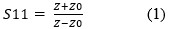
Where Z0 is the reference impedance of the system, typically 50 ohms.
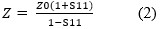
Z may be derived from the above formula:
Schematically the measurement looks like Figure 1:

A one-port measurement of a shunt impedance DUT using a VNA is reasonably accurate between about 20 ohms and 200 ohms. The reason for this is covered in reference 1.
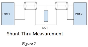
A different method is required to measure the low impedances of a power supply system. A two-port measurement is made with the unknown impedance in shunt, a “shunt-thru” measurement as shown in Figure 2.
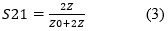
The complex reflection coefficient, S21, measured in this two-port configuration is related to the complex impedance, Z of the DUT according to equation 3:
And of course, Z can be found from the measured reflection coefficient:
This measurement configuration is suitable for impedance measurements from 0.001 ohms to 20 ohms. Conveniently, a two-port vector network analyzer (like the one in Figure 3) can make this measurement and do the impedance conversion of equation 4 in order to directly display impedance..
It should be noted that because the impedances measured are in shunt and low in value, the shield of the measurement cable can be a source of error. To mitigate this, a common mode choke should be attached between the DUT and port 2. For example, a model J2102B from Picotest is intended for this purpose and operates well from 1 Hz to 6 GHz.
Measurements
The output impedance of a low drop out (LDO) regulator will be measured with a low equivalent series resistance (ESR) 22 uF ceramic capacitor on its output with and without power applied.

The blue trace of Figure 4 is unpowered and shows the 6 dB/octave downward slope of the 22 uF capacitor which continues until resonance at 350 kHz where the equivalent series inductance (ESL) takes over and the curve turns upward. The cyan trace depicts the output impedance with power applied. A “good” response would be flat from the lowest frequency up until resonance where the curve should then climb. Note that this chart shows ohms in dB-ohms or 20*Log(Z). The starting point of the cyan trace is -25 dB-Ohms or 0.056 Ohms. The log scale is convenient for clearly seeing the 6dB/Octave rising and falling slopes.
With the power on, the peaking at 35 kHz indicates instability and would result in increased system noise at this frequency throughout the circuit. It is caused by the poor choice of the low ESR ceramic output capacitor. The data sheet for the LDO specifically states that the ESR of this capacitor must be greater than 0.5 ohms. Here is a measurement of the 22 uF capacitor alone using a shunt-thru measurement.
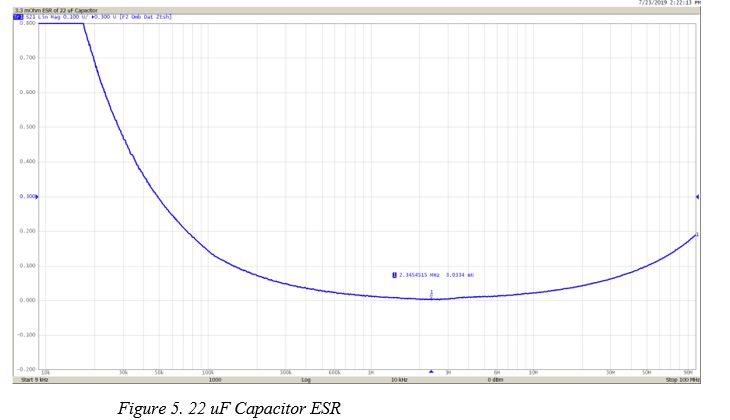
This chart, now in linear scaling, shows the bottoming out of the 22 uF capacitor impedance as the ESR of 0.003 ohms is reached (see Figure 5). Clearly, we violated the design rules for this LDO circuit.
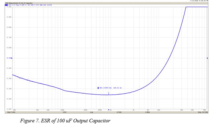
Replacing the 22 uF ceramic output capacitor with a 100 uF tantalum capacitor gives much better and flatter results as shown in Figure 6. This would have superior noise performance compared to the circuit with 22 uF.
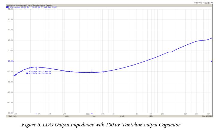
Figure 7 shows the impedance of the 100 uF capacitor with linear vertical scale. The 0.140 ohm ESR is the minimum point on the curve. It isn’t quite 0.5 ohms but is still an improvement. Clearly some care must be taken in the choice of regulator output filtering.
An ideal power supply system design would employ a number of capacitors with successively lower values of capacitance and ESL to bring the impedance curve back down as it begins to rise on the ESL of the next largest capacitor. It is important to manage this impedance. Trouncing it with an unplanned, over-abundance of capacity will result in “valleys” which will also result in greater system noise.
Making the Measurements
Measurement probes are useful tools for making these impedance measurements

Figure 8 shows the tip of a one-port measurement probe. There are also two-port probes with a single tip for making shunt-thru measurements. A homemade probe may also be constructed from simple materials. The one shown in Figure 9 is comprised of 0.141” semi-rigid coax, a female SMA connector, and a spring pin (pogo pin). The spring pin was affixed to the coax with copper tape and then soldered. A probe such as this might be useful up to about 1 GHz. Commercially made probes like the one above will have much higher bandwidth.

For accurate impedance measurement, it is important to move the reference plane to the end of the probe. This can be done by first performing a full calibration at the cable ends and then using port extension to move the reference plane.
How To De-Embed with the S5065 VNA
The automatic port extension feature of the S5065 VNA removes the added loss of the probe. An even better calibration can be obtained by calibrating to the cable end and then de-embedding the probe. The de-embedding feature comes standard with the Copper Mountain Technologies S2VNA software).
De-embedding requires the full two-port S-Parameters of each probe. These can be obtained using the Vector Mixer Calibration feature of the VNA. First calibrate to the ends of the cables using a good mechanical calibration kit. Then create a new calibration kit entry with zeros entered for the open capacitance and short inductance and delays set to zero and select it. I named this kit “Fake”. The kit entries are shown below in Figure 10.
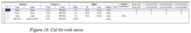
This kit assumes that the short and open will be applied directly to the tip of the probe with no delay and no fringing capacitance or inductance in the short. This isn’t strictly true but won’t greatly affect the accuracy in these measurements.
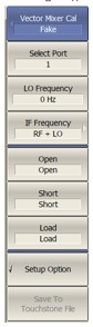
Navigate to the Vector Mixer Calibration screen and apply an open, short, and load to the tip of the probe and click the appropriate buttons. The open can be done with the probe held aloft. A short can be done by touching center and ground to a metal surface. The load can be the measurement of a 50-ohm resistor. Click the last button to save the Touchstone file which will be used for de-embedding. The VNA will automatically enable de-embedding and apply the file to the selected port. Repeat this procedure for a second probe on port 2.
This procedure is normally used for de-embedding a reference mixer in Vector Mixer Calibration but it works quite well for this purpose as well. You might wonder how the two-port parameters are derived from the one-port measurements.
The input reflection coefficient looking into a 2-port network which is terminated with load  is:
is:

If you assume that reciprocity holds for the probe then S12 = S21. A fair assumption, and:

Now there are three unknowns. Apply the three known  open, short, and load while making the three
  measurements and one can solve for S11, S21 and S22.
After calibration and de-embedding has been done, one can make accurate measurements at the probe tips. For the shunt-thru measurements made in Figures 4-7, a pair of probes were used with both touched to the same node of the circuit.
Conclusion
Understanding how to make and interpret power supply impedance is very useful for optimized, low noise power supply design. With a simple pair of homemade probes, it’s easy to make the measurements using a compact VNA. Don’t guess whether your design is optimal when you can measure it directly!
References
1) Brian Walker, “Make Accurate Impedance Measurements Using a VNA”, Microwaves & RF, July 2019, pp. 30-36
2) A.A. Savin, V.G. Guba, O.N. Bykova, “Measurement of Electronic Component Impedance Using a Vector Network Analyzer”, UDC 621.317.33