

At DesignCon 2018, the IEEE P370 standards group announced the release of two important tools to assist all engineers for de-embedding. In the presentation by Jason Ellison and Heidi Barnes, “A NIST Traceable PCB Kit for Evaluating the Accuracy of De-Embedding Algorithms and Corresponding Metrics,” the two new tools were announced, a board kit and a de-embedding software tool.
Using standard coax connections on the ends of a device under test (DUT) allows VNA measurements calibrated to the middle of the connectors with NIST traceable standards. But when the DUT is a structure in the middle of a circuit board, such as a connector, a package or even a uniform section of transmission line, a geometry transformer is needed to connect between the coax connector of the VNA reference plane to the circuit board interface of the DUT. De-embedding the DUT from the middle of the fixtured DUT is a tricky task.
Ellison and Barnes reported on two innovations from the IEEE P370 standards group to help reduce the barriers to successful de-embedding. The first is the release of a free software tool based on MATLAB, that will perform a 2-port, impedance corrected 2x thru de-embedding.
“We opened the black box of de-embedding so engineers can see what the methodology is behind this technique,” Ellison said.
The free tool, written by Ellison, will take two S-parameters as inputs, the measured 2x thru reference fixture and the composite FIX-DUT-FIX structure. The tool automatically extracts the time delay and loss of the fixture and builds a fixture model with the precise impedance profile of the fixture which is attached to the DUT. Figure 1 shows an example of the consistency test comparing the TDR of the fixture model created with the TDR of the fixture attached to the DUT.

Figure 1. Comparison of the TDR response of the fixture model and the fixture attached to the DUT. This fixture model is then used to de-embed the DUT from the fixture.
This de-embedding software tool is posted on an IEEE gitHub website, https://gitlab.com/IEEE-SA/ElecChar/P370, and is freely available to download. This is the first of four software tools the IEEE P370 standards groups plans to release.
The second innovation the P370 group released is a “Plug and Play” board kit.
While a software tool to de-embed a DUT from fixtures on either side is valuable, equally important is being able to validate the accuracy of the measurement and de-embed process. Barnes introduced a new kit of small circuit boards designed to verify the measurement and de-embed processes.
The idea is to build small, separable fixture and DUT boards that can each be individually measured, then connected together in any combination and measure the composite structures. Any de-embed tool can be used to combine the 2x thru and FIX-DUT-FIX measurements and de-embed the DUT. The de-embedded DUT S-parameters can be compared with the separately measured DUT to verify the accuracy of the de-embed process.
“What enables this kit,” Barnes said, “is the measurement grade female to female and male to female adaptors. This means the same board can be connected to the reference plane of the VNA cable or to another board, keeping the reference plane in the exact same location of the board through all of its measurements.” The kit of eight boards and adaptors is shown in Figure 2.
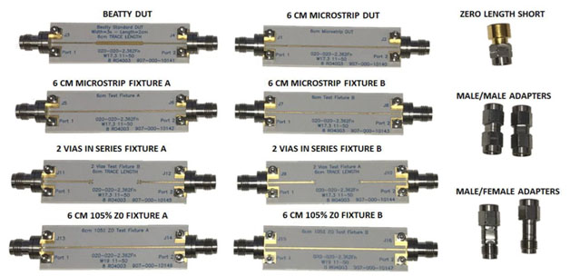
Figure 2. The eight boards included in the Plug and Play kit.
One of the many tests that can be done with this kit is to build a 2x thru FIX-FIX structure using well designed fixture or fixtures with controlled defects. Then a FIX-DUT-FIX can be measured and any de-embed tool used to extract the DUT measurement. This de-embedded DUT model can be compared with the separately measured DUT.
In one example Barnes showed the Beatty DUT measured directly and then after de-embedding. While they overlap within the pen width, Ellison said this isn’t a good enough metric. He introduced a new similarity metric, also developed in the IEEE P370 standards group, to compare the absolute and relative energy vector. Figure 3 shows a uniform transmission line as the DUT directly measured and after de-embedding with the similarity metric to quantify the comparison.

Figure 3. Measured DUT and de-embedded DUT with its similarity metric. The absolute error of the de-embedded DUT compared to the actual DUT is within 10% to over 50 GHz.
While the Plug and Play kit was developed by the P370 team, they partnered with Signal Microwave to create a commercial version, soon to be available. It is sold through DVT Solutions and can be purchased from their web site, http://www.gigaprobes.com/sparamverificationkit.html.
These two tools are the first series of products released as open source from the P370. Expect more in the next year.
See also, "First ever IEEE P370 Plug Fest Draws a Crowd".