

The 10x Probe
The name is very misleading. The 10x probe does not give you a gain of 10 between the signal at the tip on the device under test (DUT) and the input to the scope. Quite the opposite, it is really a 1/10th probe. It achieves this by adding a 9 Meg Ohm resistor in series with the tip and assuming the scope will be set for 1 Meg input. This is the 10:1 voltage divider at DC.
If this was all it did, the resulting bandwidth due to the low pass filter created by the high series resistance and the input capacitance of the cable and scope’s input capacitance would be less than 10 kHz. It would be totally worthless as a scope probe.
What enables the 10x probe to operate with a much higher bandwidth is a high pass filter in parallel with the low pass filter. By matching the pole frequencies of the low pass and high pass filters, the response of the 10x probe can be “equalized” over a high bandwidth, typically on the order of 100-500 MHz.
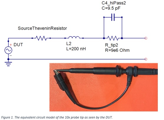
An important element to the equalization circuit is a shunt 9.5 pF capacitor across the 9 Meg resistor.
When the 10x probe is used with a long ground lead, this loop can add a loop inductance of as much as 200 nH.
The equivalent circuit model of the 10x probe’s tip, as seen by a device under test (DUT), is shown in Figure 1. This circuit has two obvious consequences, and one not so obvious.
The 10x probe as a Lemon
Contrary to popular belief, the input impedance of the 10x probe as seen by the DUT will not look like a 9 Meg resistor. Instead, it will look like a 9.5 pF capacitor. This may seem like it should be a very high impedance, but at 100 MHz, the impedance of a 9.5 pF capacitor is only about 160 Ohms. This is way lower than 9 Meg Ohms.
At the series LC resonant frequency, the impedance of the probe will be a minimum. With these typical values of inductance and capacitance, this series resonant frequency is about 100 MHz. The characteristic impedance of this circuit is 150 Ohms.
This means that frequency components at 100 MHz will get through the tip. Depending on the associated series resistance of the source, the Q of this circuit could vary from less than 1 to more than 10 when the source resistance is much less than 150 Ohms. With high Q comes more peaking in the transfer function and more apparent ringing measured by the scope at the resonant frequency.
Of course, one solution is to use a smaller loop at the tip which pushes this resonant frequency above the bandwidth of the probe.
Two kinds of engineers….
There is another important consequence of using a large loop at the tip. When we pull the signal and return conductors farther apart, we are also creating an antenna. Any tip geometry other than coaxial will be susceptible to pick up from the local RF environment.
This is why we often say, “There are two kinds of engineer, those who are building antennas on purpose and those who are not doing it on purpose.”
The more susceptible the tip geometry, also, the more efficient it is at radiating. This means current flowing in the signal-return loop will radiate.
When we probe a high bandwidth source, like a digital signal with a few nsec rise time, we usually think that the 10x probe is a high impedance and does not draw any current from the DUT. But, if the signal rise time as 3 nsec, the bandwidth of the signal is 0.35/3 nsec ~ 100 MHz. At 100 MHz, the impedance of the 10x probe is 160 Ohms. For a 3.3 V signal with a 3 nsec rise time, there can be as much as 20 mA of current in the tip’s loop, at 100 MHz.
The consequence of this is that the process of probing a high bandwidth circuit is to convert some of the signal on the board into radiated emissions in proximity of the board.
When you try to measure the cross talk on one pin while measuring the switching signal on an adjacent pin, you run the risk of measuring not the cross talk on the pin, but the inductively coupled noise from the aggressor probe to the victim probe. This can be a large signal.
As an example, Figure 2 shows the measured signal from one 10x probe looking at a switching digital signal and the near field pick up noise from an adjacent 10x probe with its tip and ground lead shorted together but not connected to anything. The inductively coupled cross talk noise between the probes is as much as 1.5 V peak-to-peak with a 3.3 V switching signal. Note also that the ringing frequency from the transient edge excitation is about 100 MHz, the series resonant frequency of the tip inductance and the 9.5 pF shunt capacitor.

The unexpectedly large currents that flow in the tip-ground loop will couple to any other 10x probe in proximity. When using two probes in proximity this coupling can add an artifact to any low-level signal you try to measure. You may think you are measuring the voltage noise on another pin, but in reality, you are measuring the inductively coupled pick-up noise from another probe’s near field radiation.
Lemonade with 10x probes
This problem of a 10x probe being sensitive to near field pick up can be turned into a feature. By shorting the tip and ground lead, we now have a pick-up coil which can sniff changing magnetic fields. This probe can be used to evaluate the near field radiated emissions from a circuit board. Such emissions can be a prelude to possible far field radiated emissions which can fail an EMC test.
The design of the layout of a circuit board will dramatically affect the amount of radiated emissions from the board. The purpose of a ground plane is to provide a low impedance for return current and confine the return current in proximity to the signal path.
When return paths are messed up, so that they are not a continuous plane, but are planes with gaps or as discrete wires, the near field radiated emissions from the board can dramatically increase. When currents flow through these signal-return path loops on the board, the resulting emissions can be picked up by a nearby 10x probe loop.
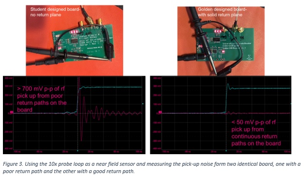
Figure 3 shows an example of two boards, each with identical circuits, but different return paths. The near field pick up in the 10x probe is more than a factor of 12 higher in a board with a poor return path compared to a good return path.
The circuit in each case was identical, just a timer chip driving a hex inverter which drove about 100 mA total into three LEDs. One of the I/O from the hex inverter was used as a trigger signal and measured by the scope using an SMA connector off-board to a coax cable.
The scope probe was moved around the board to find the position of maximum pick up of the near field noise. On the board with returns composed mostly of individual traces, the inductively coupled pick up noise is as much as 700 mV peak to peak. On the board with a continuous return path, the pick-up noise in worst case is less than 50 mV peak to peak. This is a dramatic example of the importance of the return path design to reduce emissions.
It should always be noted that just because there are strong near field emissions from a board, it is not an indication of the far field emissions that might be expected from the board. Some of the near field emissions may drop off much faster than the 1/r dipole emissions which contribute to the far field and can fail an EMC test.
Summary
When dealing with signal bandwidths higher than 10 MHz, the input impedance of a 10x probe is much lower than its 9 Meg input resistor. The tip loop inductance can act like an antenna and both radiate from the signal it measures and pick up noise from other probes. When using a 10x probe, watch out for these subtle artifacts.
On the other hand, if you want to sense the near field emissions from a board, you can take advantage of the antenna properties of a 10x probe tip-loop inductance. Afterall, every lab has at least one.