
If you want to reduce the near end channel to channel cross talk in a differential pair, is it better to use tightly coupled or loosely coupled differential pairs? Take a moment to write down your answer so you can’t change it as you read this.
I ask this question in all my signal integrity classes both as short courses to professional engineers and to graduate students at CU, Boulder. 99% of the answers are, “Of course, tightly coupled differential pairs have less cross talk. Isn’t that why we want to use tightly coupled differential pairs?” And they are all wrong.
Cross Talk and Fringe Field Lines
The fundamental root cause of cross talk is fringe electric and magnetic fields from the signal and return paths of one transmission line coupling to another. Figure 1 shows the fringe electric field lines between two microstrip transmission lines using Mentor Graphics HyperLynx.
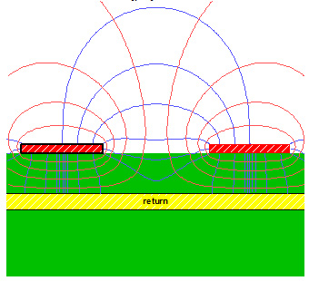
Figure 1. Fringe electric field lines in blue between two surface traces.
The combination of the electric and magnetic field coupling plus the direction of propagation of the signal down the aggressor line, result in the very different signatures of cross talk picked up on the victim line, traveling in the backward and forward directions.
The near end noise, traveling in the backward direction compared to the aggressor signal, has contributions from both the electric and magnetic field. In the circuits perspective, the near end noise is the sum of the capacitively and inductively coupled noise.
The less fringe field coupling between the aggressor and victim lines, the less cross talk noise. Two key features of the board design can directly impact the fringe field coupling. Since the magnitude of the fringe fields drop off dramtically with distance from the edge of the aggressor, the first feature is to move the victim line farther from the aggressor line. The farther the victim is from the aggressor, the fewer fringe fields it will interact with.
But equally important is to bring the return plane in closer vicinity to the signal lines. This will shape the fringe fields so they do not spread out as much. For the same edge to edge spacing, a closer return plane means less cross talk. Of course, this also means a lower characteristic impedance. If you care about cross talk and want to do all you can to reduce it, you want to live with as low a characteristic impedance as you can get away with.
Cross Talk in Differential Pairs
In a differential pair, the channel to channel cross talk is dominated by the coupling between adjacent lines in the differential pair. Figure 2 is a map of the fringe field lines between two differential pairs.
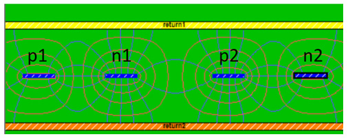
Figure 2. Example of two differential pairs with fringe fiend lines between adjacent channels.
Even in the case of the tightest coupling between the p and n lines in pair 1, most of the cross talk between pair 1 and pair 2 is coming from the coupling between adjacent lines n1 and p2. The coupling between n1 and n2 is less than 10% as between n1 and p2. However, this still suggests that if we use tightly coupled differential pairs, there will be a little be of cancellation of the field lines from n1 on p2 and n2. After all isn’t a little bit better than none? But this is not the whole picture.
The Whole Picture
If we add the constraint that we want to compare the same 100 Ohm differential pairs, with 5 mil wide traces, between tight or loose or no coupling, for the same edge to edge channel separation, a different picture emerges.
In order to maintain the same 100 Ohm differential impedance, and the same 5 mil wide lines the only design knob to compensate when changing the coupling is the dielectric spacing between the signal Ines and the planes.
If we start with a 100 Ohm tightly coupled stripline pair, and pull the lines farther apart to loosely coupled, while maintaining the same differential impedance, the dielectric spacing will have to decrease. If we reduce the line to line coupling in the pair, we must increase the line to plane coupling to maintain 100 Ohms. The planes will be closer to the signal lines. In this case, the fringe field lines should be more confined to the vicinity of the aggressor signal and there will be less noise picked up from the n1 to p2 channel.
Here is the counter intuitive part. Given the two constraints of 100 Ohm differential impedance and fixed line width, when the p to n spacing increases, the plane spacing shrinks and the channel to channel cross talk to an adjacent trace decreases. The tiny difference in cancellation of the noise from the n1 line on both p2 and n2 is completely negated by the much lower coupling between n1 and p2.
The way to see this is to put in the numbers with a field solver. In this example, I used Mentor Graphics HyperLynx. Figure 3 shows the case of three structures with tightly coupled, loosely coupled and uncoupled pairs, drawn to scale for 100 Ohm differential impedance and 5 mil wide traces.
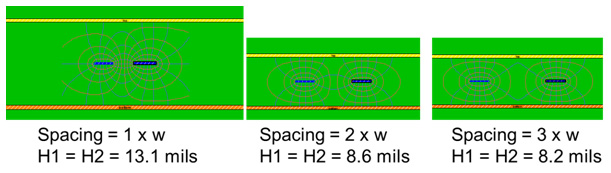
Figure 3. The geometry for three different cases of coupling, each with 100 Ohms and 5 mil wide lines, drawn to scale.
The near end differential cross talk between pair 1 and pair 2 is calculated with a 2D field solver for these three different configurations, as the edge to edge spacing between the two channels is increased. For the case of two tightly coupled pairs with the large plane to plane spacing, the fringe fields from the n1 line will extend much farther out than for the case of the loosely coupled pair.
Figure 4 is a plot of how the near end differential channel to channel noise varies as we increase the separation between the edges of the channels. For the same edge to edge spacing, the tightly coupled pairs have more than 2x the cross talk as loosely coupled pairs.
Using tightly coupled differential pairs at the board level is not driven by achieving lower cross talk, or by lower EMI. It is driven by higher interconnect density and ultimately lower cost. The requirements of lower loss, thinner dielectric and lower cross talk might drive the coupling toward loose coupling.
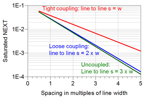
Figure 4. Maximum near end channel to channel cross talk for 100 Ohm, 5 mil wide differential pairs, as the channel to channel edge spacing increases.
Given the constrain of comparing the same differential impedance and the same line width, loosely coupled differential pairs have less cross talk. If we just compare different couplings in a pair, without changing the plane thickness, or line width, tightly coupled pairs will have slightly less channel to channel cross talk than loosely coupled, but then we would be comparing 100 Ohm differential pairs with 85 Ohm differential pairs.
Special Case of No Adjacent Planes
This example has been with the special case of an adjacent return plane. This plane affects the differential impedance AND affects the extent of the fringe field lines. This is the case at the board level where traces are microstrip or stripline.
However, when there is no adjacent return plane, the fringe fields extending from a differential pair is strongly dependent on the lines’ coupling. Tighter coupling will shape the fringe field lines to be local and not extend very far to adjacent channels.
In this case, with no adjacent return plane, tighter coupling will always result in less channel to channel cross talk. This is the environment of connectors, twisted pair cables, ribbon cable, vias, and even some leaded packages.
Which results in lower channel to channel cross talk, tightly coupled or loosely coupled differential pairs? It depends, but now we see the decision factors to answer this “it depends” question.