

Many of my clients are working with on-board and external power conversion circuits, and one of the most common requests is for advice on designing the power input filter. My colleague, Dr. Todd Hubing, goes through the calculations during many of his webinar-based EMC design trainings, but sometimes we want quick and easy guidance as a starting point.
First, let us take a look at a conventional AC mains filter topology commonly used for off-line switch-mode power supplies (see Figure 1). Note that the typical filter uses the common mode choke for both differential mode (DM) and common mode (CM) filtering. The X capacitor works in conjunction with the DM inductance of the choke to filter DM noise currents, and the two Y capacitors work in conjunction with the CM inductance of the choke to filter CM noise currents. That’s why it’s important to check both the DM and CM impedance curves of the choke you wish to specify in an application.

I have explained the difference between DM and CM currents in past trainings as well as in Volume 2 of my EMC Troubleshooting series, "Workbench Troubleshooting EMC Emissions," so this review will only touch briefly on the distinction. In a nutshell, DM currents are the main switched power input current, as depicted in Figure 2, while CM currents are those "common" to the power input wires and referenced to chassis structure (or "Earth," if there is no chassis), shown in Figure 3. Both noise currents need to be reduced prior to the main’s input in order to meet compliance limits for emissions.
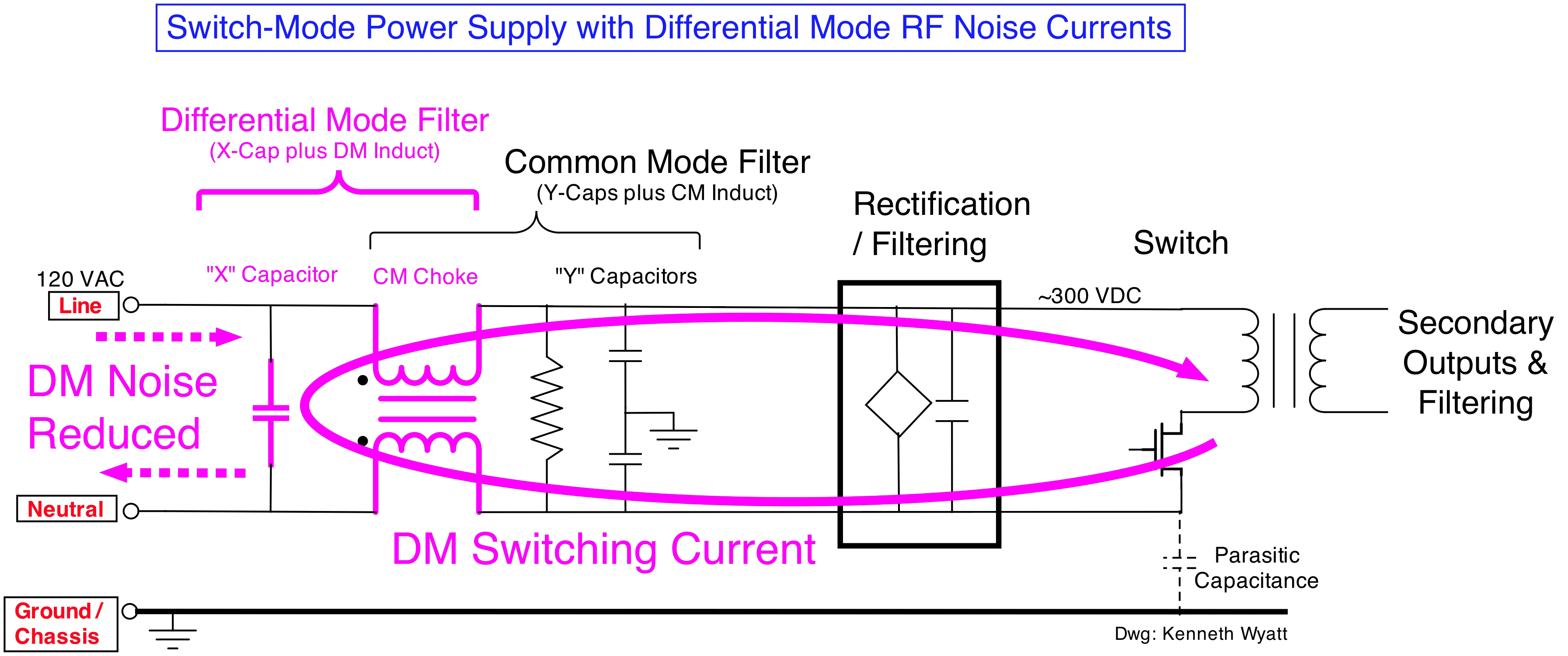 Figure 2. Shows the path of DM noise currents with the associated components of the filter that serve to reduce this.
 Figure 3. Shows the path of CM noise currents with the associated components of the filter that serve to reduce this.
While we can easily use a LISN to measure the total conducted emissions (CE), the resulting spectrum doesn't really help us identify whether we need more DM or more CM filtering. What would really be helpful is an instrument that can not only tell us the CE but display the DM and CM noise currents as well. This is where the EMZER EMScope comes into the picture.
Product Description
The EMScope is an all-in-one instrument that contains two 50µH LISNs and a spectrum analyzer covering 9 kHz to 30 MHz and with an option can extend to 110 MHz. It can display conducted emissions (Line-Gnd, Neutral-Gnd), DM, CM, or a combination of all four in a single display. It also has peak, quasi-peak, and average detectors, and can display any combination or all three together. Because EMScope is a real-time FFT-based analyzer, the sweeps are fast, with updates for all displayed traces about every second.
The unit I borrowed for this review included test limits for CISPR 15 (luminaires) and CISPR 32 (IT and multimedia), but other limits are easily programmed and stored, including MIL-STD limits. In addition, test setups and resulting displayed data can be saved and loaded. There's also a report generator, though I did not try it.
The rear panel includes a conventional Ethernet port, an optical port that connects through an optical-to-USB adapter, and two AC mains connectors (one for the LISNs and one for the spectrum analyzer). I used an isolation transformer between the LISN power input and mains to help isolate existing EMI on the line. A picture of the general test setup is shown in Figure 4.
 Figure 4. Test setup of the EMZER EMScope, switchable filter, and EUT (one of my AWG instruments). An optical-to-USB adapter connects the EMScope to my laptop.
Technical Specifications from Data Sheet
- Receiver: 9 kHz to 30 MHz (to 110 MHz, option)
- Meets CISPR 16-1-1, 16-1-2 standards (compliant QP and Ave detectors down to 10 Hz PRF)
- Ethernet Connection: Standard
- Detectors: Peak, Quasi-Peak and Average
- Measurement Types: EMI (line and neutral) and Modal (CM and DM) conducted emissions
- Full Spectrum Measurement Time: Equal to the measurement dwell time (1 to 15 seconds)
- Resolution BW Filters: 200 Hz, 9 kHz, 120 kHz (CISPR) and 1 kHz, 10 kHz (MIL-STD)
- Internal LISN: Single phase 16A, 50 µH (230 Vac, max), fully compliant to CISPR 16-1-2
- EUT Power Supply Operating Range: DC to 60 Hz
- Dimensions: 9.9 x 7.7 x 17.25 in.(252 x 195 x 438 mm)
- Weight: 18.7 pounds
Options
- Extended upper frequency of 110 MHz
- Time Domain Analysis (Scope mode)
- Fiber Optic Converter to USB
- Fiber Optic Converter to Ethernet
Initial Impressions
Upon comparing the actual unit to the pictures on the EMZER website, it seems that the photos do not quite set the right expectations. This instrument is rather large and might be better suited on a large, dedicated test bench with a decent ground plane on top. With a depth of 17.25 in., it's a little too long for my regular troubleshooting work bench.
What I really loved about this system was the web-based control panel! I am always leery about having to install special software and associated drivers on my laptop. With EMScope, you simply open your browser and type in its web address. After the EMScope connects, you have a screen similar to the one shown in Figure 5.
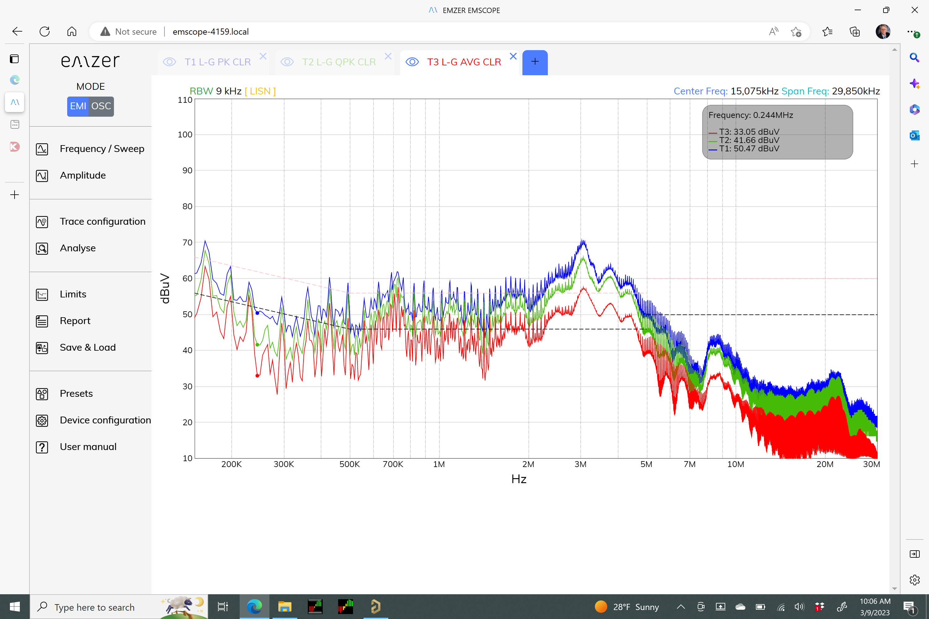 Figure 5. EMScope display showing conducted emissions Line-Gnd with peak, quasi-peak, and average traces for an unfiltered 500 W power supply. These three traces were displayed simultaneously within about one second.
The main control panel on the left allows the setting of frequency limits, bandwidth, amplitude scaling, displayed traces, analysis tools, and test limits. There's also a reporting tool, the ability to save and load setups, overall setting configuration, and a handy user manual.
One thing not intuitive was that, in order to display multiple traces, you must first click the blue "+" button along the top edge of the display. This will add a trace. Then you can go to the "Trace Configuration" button in the main menu to set the trace measurement parameters. My first inclination would be that the function to add and delete traces would belong directly in the Trace Configuration menu.
There is also a spectrogram (or "waterfall") display feature for analyzing pulsed, conducted, or modal emissions. I did not play with this much, as the EUTs I was using had a constant emissions profile. EMZER has an application note on how to use this feature.1,2
Filter Demonstration
The evaluation unit came with a sample 500 W power supply that had some of the filtering components removed. There was also an external filter test assembly with switchable "through" (no filtering), DM filter (220nF X-cap), a CM filter (2.2 mH CM choke), and a combination of the two. This was useful in evaluating the differences in filtering while displaying several combinations of data.
 Figure 6. Resulting Line-Gnd conducted emission plots (peak, quasi-peak, and average) when switching in the 2.2 mH common mode choke on the external filter.
Figure 6 shows the resulting plots (peak, quasi-peak, and average) when just the 2.2 mH common mode choke is switched in. Compare this to the unfiltered plots in Figure 5 above. Shown is the Analyze menu, which allows the addition of markers and math functions for delta measurements.
Here's where Würth Elektronik's "Design Your Own Filter" kit (part #744 998) can come in handy.4 Using the supplied technical manual helps choose appropriate components. These fit into the universal PC board and can be used to try out different filters.
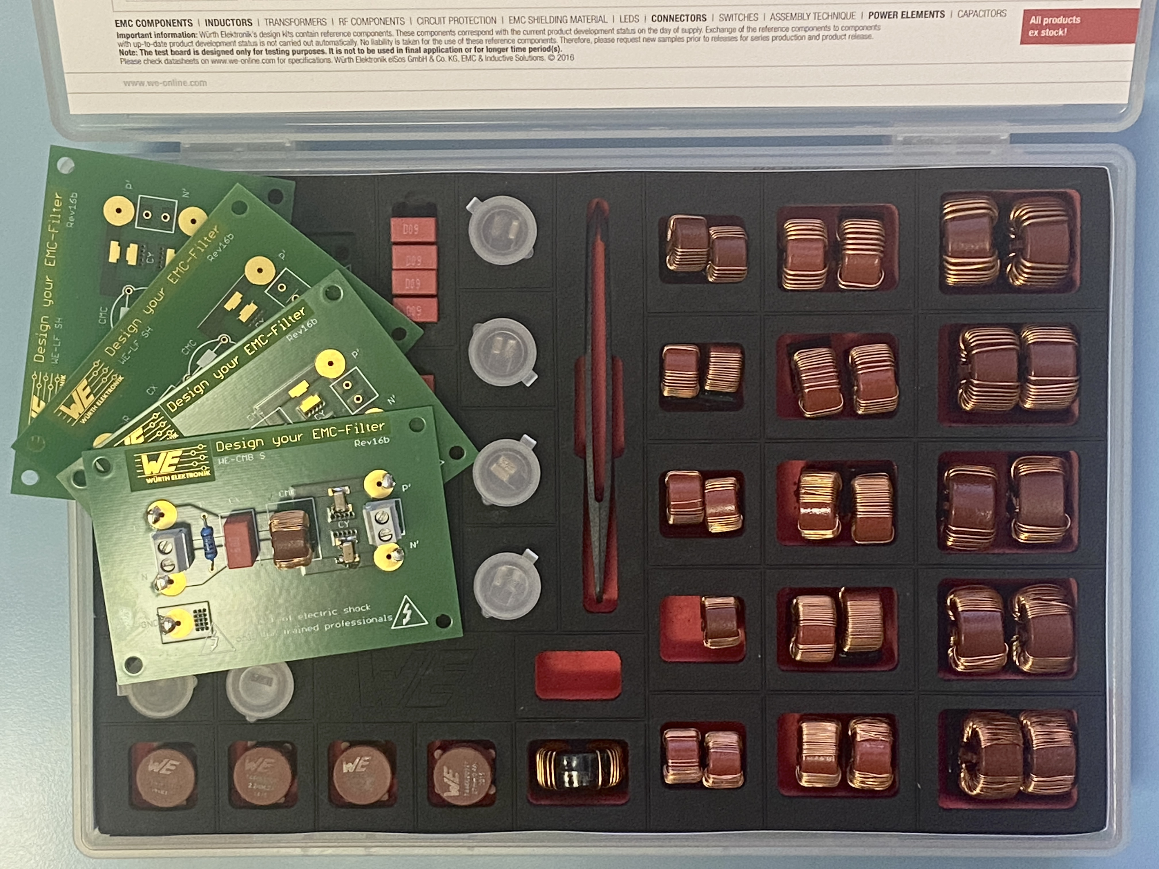 Figure 7. Würth Elektronik's "Design Your Own Filter" kit with technical manual comes in handy for quickly trying different filter topologies.
LED Lamp Demonstration
I have previously made conventional conducted emissions measurements of the earliest LED lamps and thought it might be fun to measure some using the EMScope.5 The first example is a Lowe's Hardware house branded Utilitech Pro model G2560F 60 W equivalent lamp circa 2010 (see Figure 8). Figure 9 shows the DM and CM emissions separately and we can see that the DM noise currents (in green) dominate. An X capacitor added across the mains input should help reduce this.
 Figure 8. The older Utilitech Pro lamp being tested. This is one of the first-generation LED lamps, available about 2010.
 Figure 9. The DM and CM quasi-peak emissions from the Utilitech Pro lamp superimposed over the CISPR 15 limits for luminaires. It fails horribly.
On the other hand, I tested a recent Kroger "Every Day Living" 60 W equivalent lamp, which gave excellent results (see Figure 10). We can see the DM currents still dominate, but are well under the CISPR 15 limits.
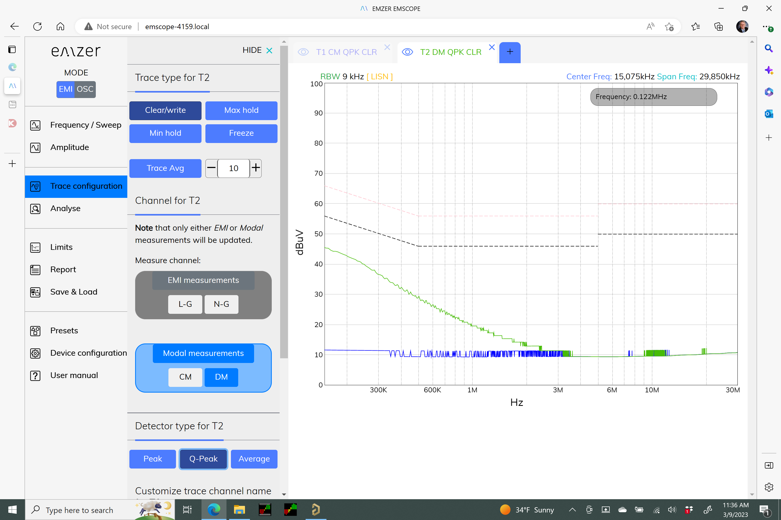 Figure 10. The DM and CM quasi-peak emissions from Kroger's "Every Day Living" lamp was well under the CISPR 15 limits for luminaires.
One last counterintuitive instruction not explained in the manual is that to switch from EMI to modal measurements (see secondary menu panel in Figure 9 and Figure 10), you must click the choices (EMI or Modal) panels prior to clicking on the L-G/N-G or DM/CM buttons. Once this was explained to me, I was able to display any combination of multiple EMI or modal traces.
Measuring DC-Powered EUTs
The EMScope LISN input can handle DC through 60 Hz power at up to 230 Vac in its built-in 50 µH LISNs. Alternatively, you can use external LISNs (5µH, for example,) by removing the two front panel jumpers and connecting the LISN outputs directly to the analyzer inputs. Figure 11 shows a pair of Tekbox 5 µH LISNs connected to EMScope and measuring a sample DC-DC converter.
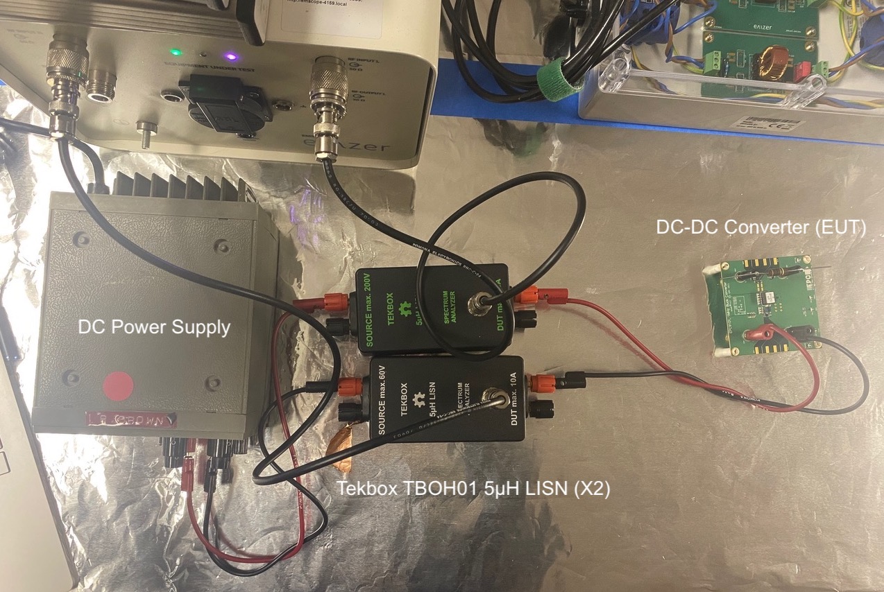 Figure 11. Test setup when using external LISNs with the EMScope. The LISN outputs connect to the analyzer inputs (top N-connectors).
Summary
The EMZER EMScope is a powerful and versatile instrument for measuring and displaying any combination of conducted emissions (L-G/N-G) and modal CM/DM scans using either peak, quasi-peak, or average detectors. The FFT-based dual-input real-time spectrum analyzer is fast and there's nearly unnoticeable lag between measurement scans. This makes it easier to select the appropriate filter components required for a given EUT.
The web-based user interface is easy to connect to and relatively intuitive and, best of all, it does not require specialized software or drivers. While there are alternate methods for splitting DM and CM noise currents6, EMScope provides an "all in one" solution for displaying both conducted emissions and the modal DM and CM emissions in a single display.
Price class: $9,000 to $14,000, depending on options. The U.S. distributor is Absolute EMC.
REFERENCES
1. Emzer: www.emzer.com
2. Emzer Resources, "EMScope Brochure" and "EMScope Operating Manual," https://emzer.com/wiki/doku.php
3. Absolute EMC (U.S. distributor), www.absolute-emc.com
4. Würth Elektronik, Design Your Own EMC Filter Kit, https://www.we-online.com/en/components/products/DESIGNKIT_744998
5. K. Wyatt, "Comparing conducted emissions from LED lamps," https://www.edn.com/comparing-conducted-emissions-from-led-lamps/
6. K. Wyatt, "Review: Tekbox LISN MATE is valuable for evaluating filter circuits," https://www.edn.com/review-tekbox-lisn-mate-is-valuable-for-evaluating-filter-circuits/