The development of 5G communications, sophisticated sensing, and radio-determination applications are pushing designers and developers into higher frequency bands. The bands that were once reserved for satellite communications and radar applications are now being opened for broadband solutions and are becoming more commonly integrated in everyday devices.
The development of millimeter wave (mmWave) applications is an exciting new area, with frequencies extending into the hundreds of gigahertz and even to a few Terahertz, or 1012 Hertz (1,000,000,000,000). The expansion of this frequency use has been quite remarkable over the past 20 years with materials scientists and physicists applying micro-structure and doping to create devices that can be used to generate usable signals.
This article discusses a brief introduction about the fundamentals of how these signals are generated, what applications mmWave techniques are suited, some important characteristics of mmWaves, and some of the challenges of measuring emanations at these high frequencies.
mmWave Generation
First, “where” do mmWaves exist? In short, the traditional spectrum is from 30 to 300 GHz.
Given the wavelength versus frequency relationship:

So, the wavelength of the mmWave ranges from 10 mm (30 GHz) to 1 mm (at 300 GHz). In general, “mmWave” uses now extends well beyond 300 GHz with some devices operating up to 1000 or 2000 GHz (or 1 to 2 terahertz, THz) Designers are using these higher frequencies for increased bandwidths and uses beyond the already-crowded spectrum.
Interestingly, mmWaves are not new; the first experiments with mmWave frequencies took place over 100 years ago! Jagadish Chandra Bose, who was born in Mymensingh, India was able to generate, characterize, and analyze short wavelengths [i] during the years of 1894-1900. Bose was primarily interested in the scientific study and analysis of 5 mm long waves (or frequencies of 60 GHz). This early work included the characterization of reflection, refraction, and polarization of these waves.
One common method of generating mmWave is to employ Gunn diodes (also known as transferred electron devices), which are passive devices that can be doped to create ‘negative resistance’ characteristics under certain DC biases. The effect is that the current decreases as the voltage increases, which creates oscillations that are a function of the materials and external components. These devices can be adjusted for single frequency outputs.
Several developers use the non-linear behavior of diode mixers to up-convert to mmWave frequencies. This is achieved by sweeping a lower-frequency signal generator into a frequency multiplier, which is tuned and filtered to up-convert the frequency into a higher band.
In Figure 1, a signal generator has a range of fl to fh. By injecting a sufficiently strong signal into the input of the frequency multiplier, the range of the signal generator can be increased by n times. The parameter ‘n’ is a function of the device design,
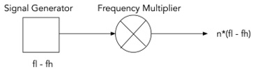
Figure 1. Frequency Multiplier
The frequency multiplier, a non-linear device, will create output frequencies of between n*fl and n*fh. The challenge for metrologists is establishing and measuring a calibrated output power that can be used as a communications media.
Propagation of mmWaves has an inherent limitation, and benefit, of employing these frequencies in fixed and mobile communications networks. The high frequency naturally comes with a high propagation loss, which is a function of the frequency/wavelength of the electromagnetic wave.
For example, the propagation loss is found from the following well-known equation:

One can see that the propagation loss increased with the square of the distance. This is because the energy radiates akin to the surface of a sphere, see Figure 2.

Figure 2. Radiation Propagation[ii]
In the equation, R is the distance between two antennas, in meters. Converting to dB and converting the wavelength to equivalent frequency, the equation becomes:
PL dB = 92.4 + 20Logf(GHz) + 20 logR(km)
At VHF frequencies (30-300 MHz) the propagation loss is between 62 dB/km and 82 dB/km. This allows for many miles of propagation before the signals naturally decay.
At 100 GHz, however, the propagation loss is 132 dB per km. This means that, in general, mmWave transmissions don’t inherently propagate over long distances without serious antenna gains in the system. This also means that any long-haul systems will be largely point-to-point arrangements. This has the inherent benefit that frequency re-use in tight geographical spaces is possible with reduced interference between systems. This will be important in future 5G connectivity scenarios, discussed below.
The FCC, in its 1997 publication OET Bulletin 70, foresaw the implications of natural behavior:
“While signals at lower frequency bands can propagate for many miles and penetrate more easily through buildings, millimeter wave signals can travel only a few miles or less and do not penetrate solid materials very well. However, these characteristics of millimeter wave propagation are not necessarily disadvantageous. Millimeter waves can permit more densely packed communications links, thus providing very efficient spectrum utilization, and they can increase security of communication transmissions.”[iii]
One aspect of mmWave propagation is the atmospheric effects of oxygen and water absorption. Figure 3 shows the additional attenuation that occurs as mmWaves pass through the atmosphere. Essentially, the RF waves set up resonance conditions in the O2 and H20 molecules. The resonances absorb energy, which increases the path loss.
These absorption frequencies are bad for propagation and, hence, can be useful for intentionally limiting the range of links where the designer might not want efficient propagation, either for security or for local spectrum re-use.
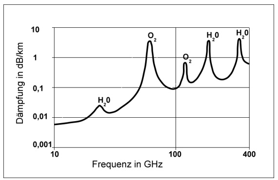
Figure 3. Atmospheric Absorption Losses
Allocations and Use of Spectrum
In the US, the frequency spectrum is managed jointly by the FCC and the US Department of Commerce National Telecommunications and Information Association (NTIA). For commercial and consumer use, the FCC Rules are generally applicable; licensing is under the authority of the FCC. For government use, which includes emergency services and government communications use, the NTIA manages the allocations.
Many changes in the use of the spectrum have occurred in the past 20 years, especially with the advancement and deployment of wireless services, both licensed and unlicensed. The shuffling of spectrum is an ongoing process. It is a global activity, largely coordinated by the World Radiocommunication Conference (WRC), which meets routinely to decide who uses what spectrum for what purpose. WRC is organized under the International Telecommunications Union (ITU), which is a global alliance that is focused on common allocations around the world.
Currently, the FCC in the United States addresses spectrum up to 300 GHz (see Figure 4). In June of 2019, the FCC released its Rules that address “Spectrum Horizons.”
Taken directly from the preamble the “Commission took steps to provide new opportunities for innovators and experimenters to develop new equipment and applications for spectrum between 95 GHz and 3 THz, frequencies that only recently are becoming well-suited for the development and deployment of new active communications services and applications. The Commission adopted rules for a new class of experimental licenses available for the spectrum above 95 GHz that provide for increased flexibility.”
Fun stuff, more to come!

Figure 4. NTIA Frequency Allocation Chart
Much of the frequency allocations are shared between multiple users, which becomes an issue when the industry proposes to re-allocate spectrum for other uses. The incumbent users (notably space astronomers and radar operators) are not keen to share the spectrum with other users, which could pose a threat to noise-free operation.
Table 1. mmWave Frequency Band Designations:
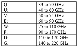
Bandwidth Bandwidth Bandwidth
5G systems are going to need extremely low latency (which is essentially the messaging delay time through a system) to achieve the system responses necessary for mobile devices, such as autonomous cars. This means that data networks will require extremely high data rates for sensing, communication, and control. Consider a vehicle moving along at 100 km/hour, which works out to 62.5 m/s. To respond to an oncoming obstacle will require system latencies in the millisecond range. As a result, the entire decision-making process, including detection and decision-making, has be very fast.
When two automobiles arrive at a four-way stop simultaneously, the car that is to the right is to proceed through the intersection first. The first Google driverless car to be involved in an accident was “following the rule” at a four-way stop intersection. The other car, driven by a human, did not follow the rule. The decision-making response time when an unintended action occurs by other vehicles must be in the millisecond range, thus the round-trip sequence needs to very fast. This puts requirements on the bandwidth as well as the system decision-making processing.
One protocol that is being rolled out is IEEE 802.11ad, which is a WiFi protocol but operating in the 60 GHz range. An industry effort, known as WiGig, is a strong proponent of 802.11ad rollout and advancement. (However as of this writing the use and promulgation of this technology has not advanced as some had hoped.)
There are several salient characteristics of these emerging technologies. First, the transmission speeds are huge (theoretically up to 7 Gbps), compared to 802.11a/b/g/n which operate at the 2.4/5GHz bands. Second, the propagation losses are large, which allows for smaller density WiFi cells. Finally, the small size allows for massive multiple-input multiple-output (MIMO) antenna arrays (see Figure 5). These arrays create the opportunity for very precise and agile beam-forming designs that allow the devices to ‘point’ at different transmission pairs; these technologies are electronically-steerable arrays, so they are very agile and can adapt to changes in local operating conditions and environment.

Figure 5. Massive Mimo mmWave Antennas (Georgia Tech)
The expectations around MIMO hold promise to underpin part of 5G, which will rely on many small cells. The future network topologies will use layers of large and small cells to increase the density of connections in future networks.
EMC Challenges
So what sorts of EMC challenges does this promising technology bring?
In a word: Measurements. The instrumentation has evolved over the past few decades to measure into the hundreds of GHz. While not a “daily event” in the life of a lab, we’re challenged to measure, with enough accuracy as we can muster, field strengths, power densities, output power, frequency tolerance, and other regulatory matters. Plus, the regulators are working hard to keep up to speed with procedures that are keeping pace with the innovation (this is hardly new).
One area of promulgation is for radar and sensing applications. These implementations are often in the 60+ GHz space and typically have swept or exotic modulations that take a very patient and cautious approach. A big bag of “skepticism” is applied when measuring these devices as what makes common sense at 50 MHz disappears at 50 GHz.
Some of the innovations that have spurred the development of technologies include mixer/downconverter devices (Virginia Diodes, Farran, among others) that can convert a spectrum analyzer with a maximum tuned frequency range of ~40 GHz into a system that peers into the hundreds of GHz. The highest frequency “thing” that we measured was a device that operated at 276GHz, which is truly remarkable. The tricky measurement part is that the wavelengths are short, so the beamwidths are very narrow, and getting an accurate measurement of the emitted energy takes a lot more time than your standard OATS measurement.
These very short wavelengths create a lot of challenges for design and test because of the mechanical precision required for making accurate measurements. In the US, the most common emissions measurements techniques are embodied in ANSI C63 procedures, notably ANSI C63.10 for unlicensed devices and ANSI C63.26 for licensed devices. Current commercial test procedures typically stop at 18 GHz, that is, there are few established methods for measurements in the mmWave region, much less calibration and verification techniques.
In addition to procedures, challenges exist in the use and calibration of antennas which, because of the small feature size and waveguide construction, pose a different set of measurement challenges for compliance testing laboratories and test engineers.
Finally, the advancement of mmWave technologies poses interesting issues with regards to radiation effects on human beings. The FCC, and others, are looking at methods to allow the use of these frequencies and technologies, while still preserving the protection against human exposure, which is part of their purview.
Other EMC matters are nominally the practical issues of spectrum crowding, suppression techniques for very short wavelengths and, more to some of the core of our community here: signal integrity in the sub-nanosecond to pico-second world. The very art of high frequency board design strains the design process to make sure that signals are spectrally efficient and propagation issues are controlled.
Promise for the Future
The extension of operating frequencies in the mmWave region and beyond is the story of the wireless development for the next thirty years. Understanding the challenges and improving the state-of-the-art is a key driver for the EMC and wireless industries.
[ii] http://hydrogen.physik.uni-wuppertal.de/hyperphysics/hyperphysics/hbase/forces/imgfor/isqrr.gif
[iii] FEDERAL COMMUNICATIONS COMMISSION OFFICE OF ENGINEERING AND TECHNOLOGY Bulletin Number 70 July, 1997 “Millimeter Wave Propagation: Spectrum Management Implications”