
With the availability of both single-ended and differential oscilloscope probes, the question often arises as to which is best for probing low-speed differential serial data signals and why. The answer depends on trade-offs involving many factors. This article provides insight into factors to consider when choosing which type of probe is best for the situation.
Single-Ended and Differential Probes: Pros and Cons
Most oscilloscopes include four single-ended passive probes. This provides a cost advantage over using differential probes, which are typically not included standard with the oscilloscope and need to be purchased separately. Single-ended probes allow for the ability to see the two input signals of the differential pair (Data+ and Data-), which serves as a consistency check that the correct signals are being probed. Commonly, a user may probe two signals which are assumed to be Data+ and Data-, but actually probe Data+ and a clock, or Data+ and Chip Select, etc. This connectivity issue would be easy to identify when using two single-ended probes, but may be challenging to detect when the wrong signals are probed when using a differential probe. Another advantage of single-ended probing is that the user does not need to be concerned with the common mode voltage range, as long as the signal does not exceed the general input voltage range.
A primary disadvantage of single-ended probes is that they occupy twice as many oscilloscope channels as differential probes do. For example, when using a four-channel oscilloscope with two single-ended probes connected to a differential signal, half of the oscilloscope channels are needed in order to view the signal. Additional disadvantages of single-ended probing includes the requirement to trigger on either Data+ or Data- rather than the differential signal (which typically is not a problem, since Data+ and Data- are mirror images of each other), and a common mode rejection ratio (CMRR) of 100:1, which, although not as much as a differential probe, is usually sufficient for most low-speed serial data signal captures.
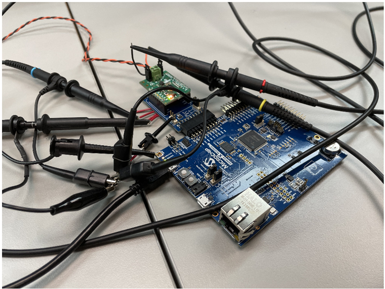 Figure 1. Single-ended probes connected to a low-speed serial data device under test.
 Differential probes have the advantage of only occupying one oscilloscope channel, which allows the ability to connect more signals to the oscilloscope for simultaneous analysis. Triggering on a differential waveform can be performed directly using a differential probe, and the differential probe’s CMRR is typically around 1000:1, providing 10x the amount of common mode rejection of most single-ended probes. Additionally, differential probes can be used as single-ended probes by connecting the negative input of the differential probe to ground.
Disadvantages of differential probes typically include the inability to see the single-ended signals, the probes cost extra and are not included standard, and the signal may unknowingly exceed the common mode range.
 Figure 2. Differential probe connected to the same low-speed serial data device under test as shown in Figure 1.
 Shown in Figure 3, two single-ended probes are connected to Data+ and Data- of a serial data signal. Since Data+ and Data- are mirror images of each other (Data- is the inverse of Data+), then the differential probe shows the same result as channel subtraction using two single-ended probes.
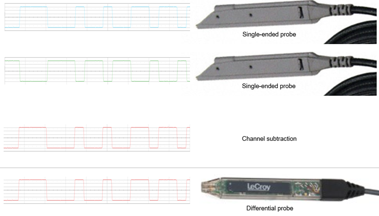 Figure 3. Channel subtraction using two single-ended probes shows the same waveform result as one differential probe.
However, if the probe connectivity of the device under test is not correct, then single-ended probes can help reveal the connectivity issue. For example, in Figure 4, rather than connecting to Data+ and Data-, the user has connected the probes to Data+ and a different serial data signal. The waveform from the differential probe shows a 3-level signal, which is not correct. Using a differential probe, it is not clear why the signal appears this way. By contrast, the two single-ended probes reveal that the second probe, which should be connected to Data-, is in fact connected to a different serial data signal which has a faster bitrate. By viewing the signals using single-ended probes, the user can quickly determine that the signal is not a 3-level signal, but rather, a result of two 2-level signals in which the second probe tip is connected to the wrong signal.
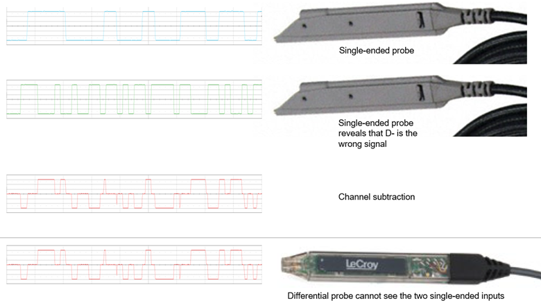 Figure 4. The differential signal incorrectly shows a 3-level waveform. Using single-ended probes reveals that the user has connected to the wrong signal instead of Data-.
Additionally, single-ended probes can reveal any asymmetry between Data+ and Data-. As shown in Figure 5, this real-world 10Base-T1S signal has overshoot on Data+, but does not have undershoot on Data-. This lack of symmetry can be detected by using single-ended probes, while differential probes only show a differential signal with half of the total overshoot of Data+.
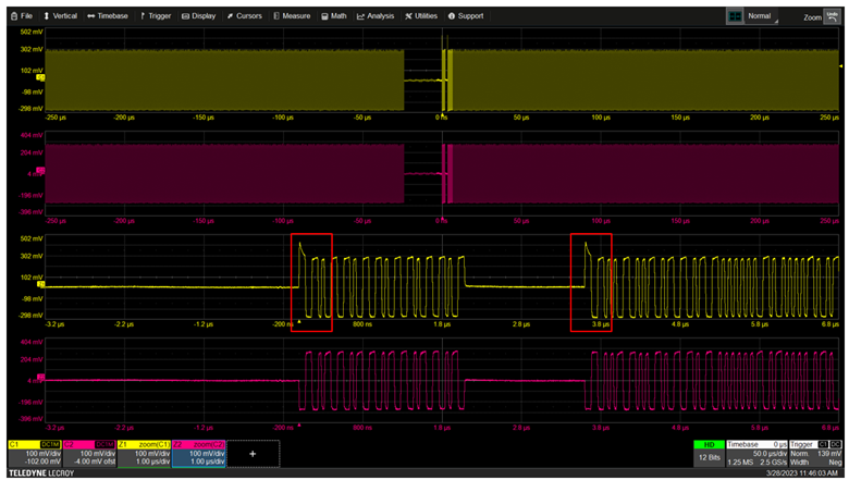 Figure 5. Data+ contains overshoot, but Data- does not contain undershoot. This asymmetry between Data+ and Data- can be revealed when using single-ended probes.
 For signals which have common mode, both single-ended (CMRR typically 100:1 with channel subtraction) and differential probes (CMRR typically 1000:1 within the probe) can be used. Since differential probes reject the common mode signal, then the amount of common mode contained in the signal is typically not shown to the user. By contract, single-ended probes can reveal the common mode signal while also rejecting the common mode using channel subtraction. This way, a common mode problem can often be more easily detected when using single-ended probes. An example of this is shown with a real-world signal in Figure 6.
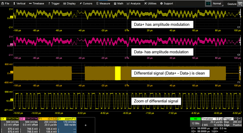 Figure 6. Data+ and Data- contain common mode amplitude modulation, which has a much larger magnitude than the actual serial data signal. Note that the single-ended waveforms (yellow and pink) have vertical scaling of +/- 2 V, while the scaling of the differential signal (orange) is +/- 800 mV. The common mode amplitude modulation has been rejected using channel subtraction, and the zoom of the differential signal shows a clean differential waveform in which the common mode has been fully removed.
 When testing signals in which the common mode voltage range of a differential probe has been exceeded, this can result in unusual waveform anomalies. As an example, Figure 7 shows a real-world double data rate clock signal acquired from a floating device under test. The differential probe is rated as +/- 4 V. Since the device under test is floating, the common mode portion of the signal is not constrained and periodically exceeds the common mode voltage range of the probe. Given that the common mode signal is incident on both the + and – inputs of the differential probe and the probe subtracts the two inputs, the waveform appears to be pinched off in amplitude when this occurs. The reason for this is that when the positive terminal of a differential probe is clipped, and the negative terminal of the differential probe is also clipped, then the subtraction of the two clipped signals (the resulting differential waveform) approaches zero amplitude. If the user was not aware of this aspect of differential probes, then they may assume that the signal under test’s differential signal was amplitude modulated. However, the differential signal was steady and level, while the common mode signal was driven outside of the common mode range of the differential probe. This problem does not occur when using single-ended probes.
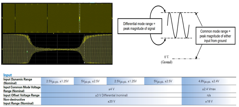 Figure 7. When the common mode range of a differential probe is exceeded, this may appear as an amplitude reduction in the differential waveform. This problem does not occur when using single-ended probes.
 In summary, single-ended probes and differential probes each offer varying advantages and disadvantages when connected to low-speed serial data signals. A table summarizing the primary advantages and disadvantages of each is shown in Figure 8. These pros and cons can help guide a decision on whether to use single-ended probes or differential probes for low-speed serial data signal integrity testing.
 Figure 8. Table summarizing advantages and disadvantages of single-ended probes and differential probes for low-speed serial data signal testing.