
Evaluation of Shielding Materials
In this article, shielding materials consisting of conductive fibers are investigated. A measurement system for evaluating the magnetic shielding capability of shielding materials is presented. From this, interrelationships of the frequency-dependent shielding effect are deepened, and relevant material parameters are obtained.
The effectiveness of a shielding is determined by the internal material parameters R', L' and C' and the material structure (fiber structure). The effectiveness of a solid, non-ferromagnetic metal shield depends on the conductivity, the skin effect, the frequency, and the material thickness. Solid metal shields work well, but are not suitable for many applications due to their lack of flexibility. Therefore, conductive fiber shields are used. With these, the internal, effective shielding relationships are much more complex.
The transfer impedance ZT is used to evaluate shielded cables. The shielding material is not evaluated separately. The transfer impedance depends not only on the shielding material, but also on the cable structure and the design of the test setup. Therefore, it is necessary to find parameters that characterize the shielding material alone.
The shielding effectiveness as describes the attenuation characteristics of the shielding material. It cannot be used to determine the material-internal electrical parameters (R', L' and C' ) and the material structure (fiber structure).
The goal is to develop parameters and measurement systems that can be used to describe the internal mechanisms and material properties of shielding materials.
The article investigates how a magnetic flux Φ can penetrate shields. The penetration follows different frequency dependent mechanisms of action.
Description of Magnetic Shield Penetration
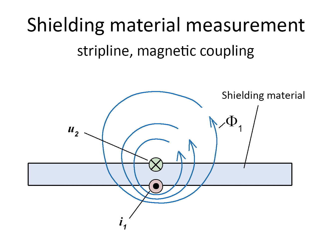
A linear propagating current i1 is applied to the bottom side of the shielding material (see Figure 1). The magnetic flux Φ 1 generated by the current ( Φ1 = L12 i1) penetrates the shielding material depending on the frequency. Voltage u2 (u = ω L12 i1) is induced on the surface of the top side of the shielding material.
Φ1 = L12 i1 (Equation 1)
u = ω L12 i1 (Equation 2)
Inductance L12 links the current i1 with the voltage u2. Inductance L12 is frequency dependent due to the skin effect. Its characteristic describes the effect of the skin effect and thus the magnetic properties of the shielding material. The voltage u2 behind the shield can cause other disturbances such as currents, magnetic fields and electric fields. In the following, the dependence of this mechanism on frequency and material structure is considered.
A special measurement chamber is used to measure the inductance L12. Figure 2 shows the setup of the measurement chamber. The shielding material is inserted into the metallic closed housing of the measurement chamber. A 50 Ω stripline (stripline 1) is located on the bottom side of the shielding material. The current i1 through the stripline takes the path through the shielding material as return path. The magnetic field generated by the current i1 penetrates the shielding material according to its shielding effectiveness. The second 50 Ω stripline (stripline 2) is located on the upper side of the shielding material. The voltage u2 is induced in stripline 2 by the magnetic flux F1.
 Figure 2. Measurement setup with striplines and measurement chamber.
The inductance L12 (L12 = -u2 / ω i1) describes how much magnetic flux Φ1 can pass through the shielding material and induce the voltage u2.
L12 = -u2 / ω i1 (Equation 3)
If there is no shielding material in the measurement chamber (see Figure 2), the reference inductance L12 of the measurement setup is measured (see Figure 3). The inductance L12 is constant over a wide frequency range. The end of the linear frequency response of the measurement chamber is reached at 1 GHz.
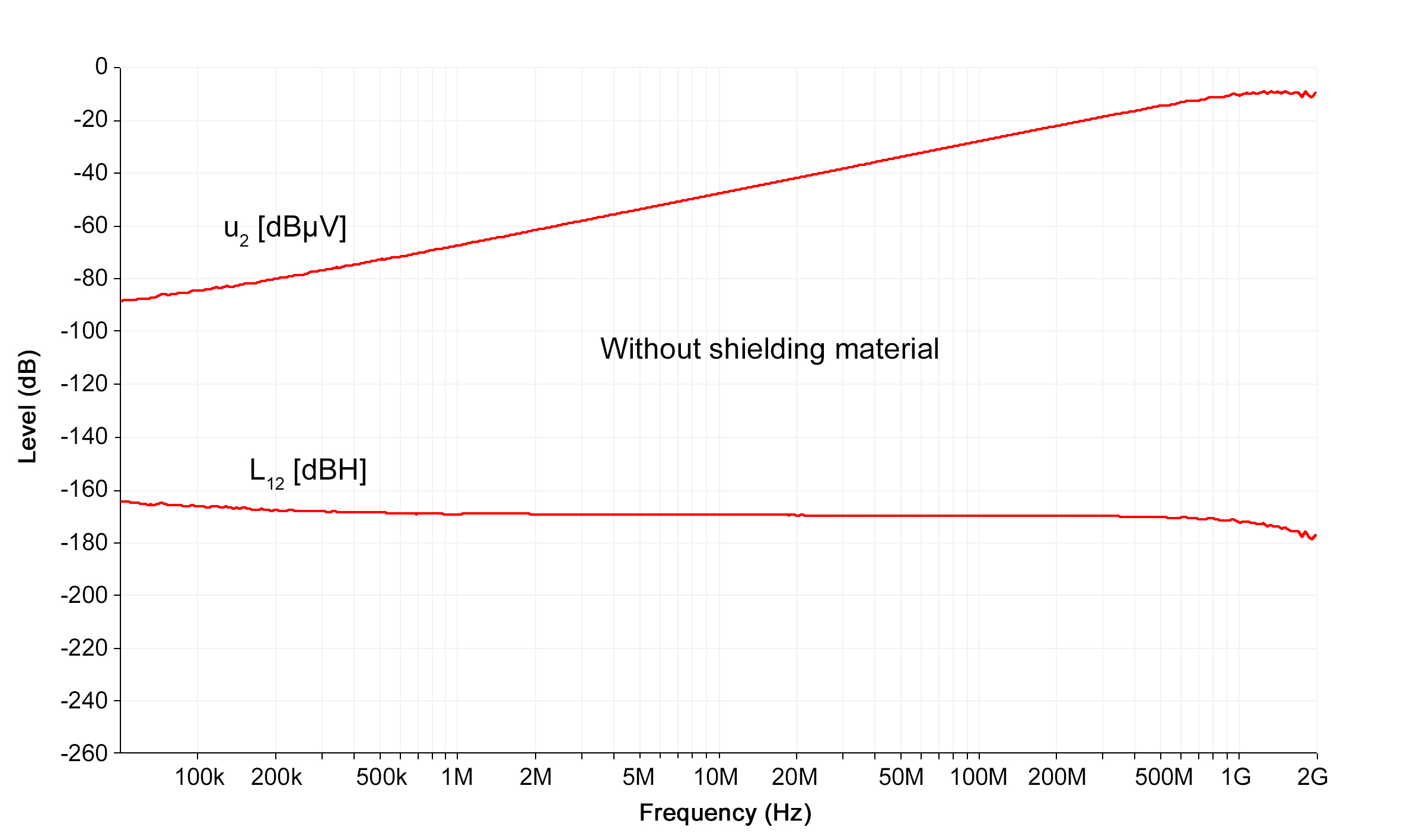 Figure 3. Frequency response and inductive coupling of measurement chamber without shielding material (i1 = constant).
 Mechanisms of Magnetic Field Shielding
The voltage u2 induced by the magnetic field (see Figure 4) is tapped by the stripline 2 as u'2. This voltage is slightly smaller than the voltage u2 at the surface of the shielding material, because there is still magnetic field passing through the space between the stripline and the shielding material. This effect is neglected in the following and u'2 is considered as identical to u2.
 Figure 4. Tapping of the voltage u2 with a stripline. The voltage u2 that is induced in the stripline (see Figure 5) depends on the effectiveness of the magnetic shielding of the shielding material. The associated inductance L12 describes the magnetic penetration of the shielding material. Figure 5 shows the induced voltage u2 and the inductance L12 for the shielding material S10.
 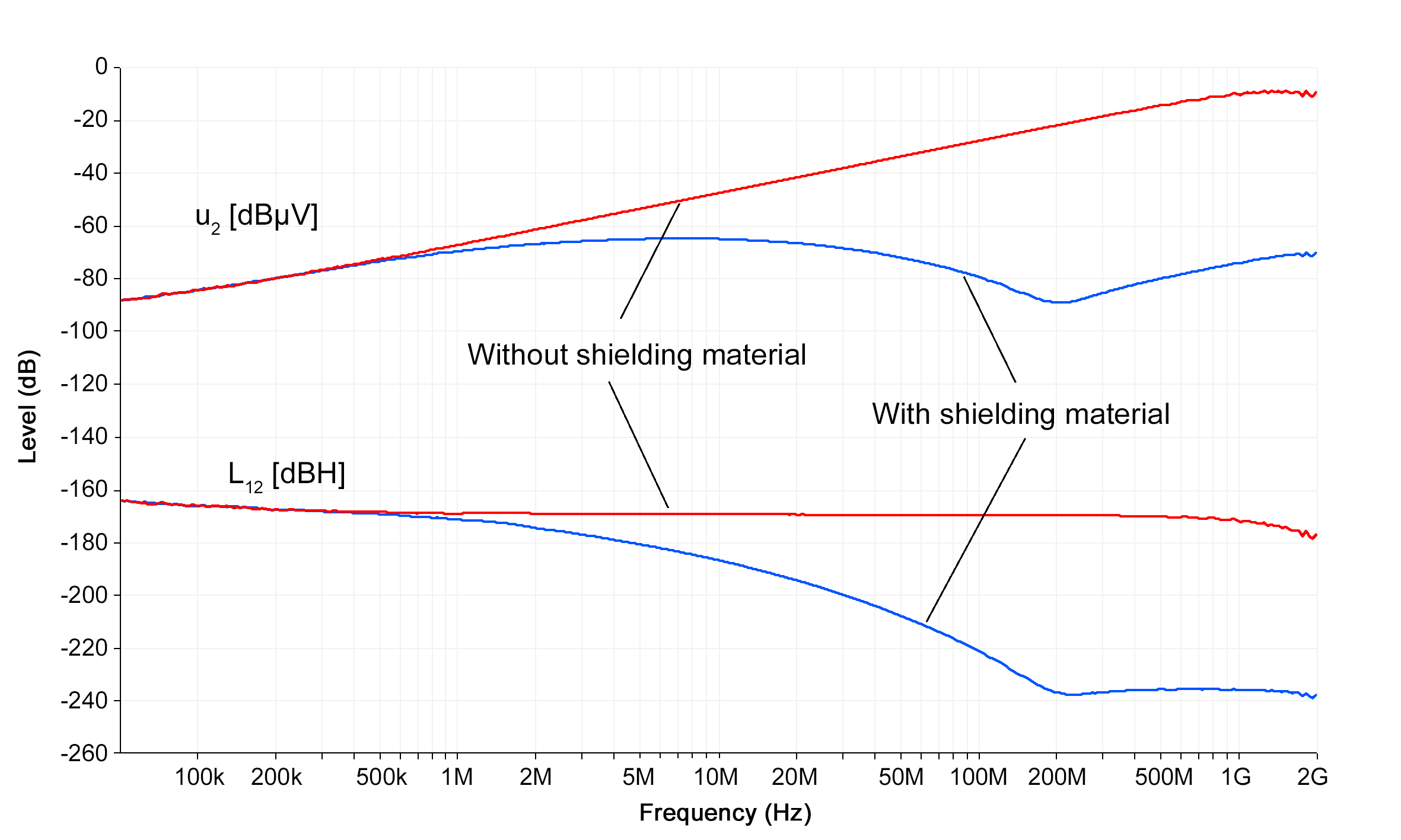 Figure 5. Inductive penetration of the shielding material S10.
 The shielding material S10 is a flexible, metallized nonwoven (see Figure 6).
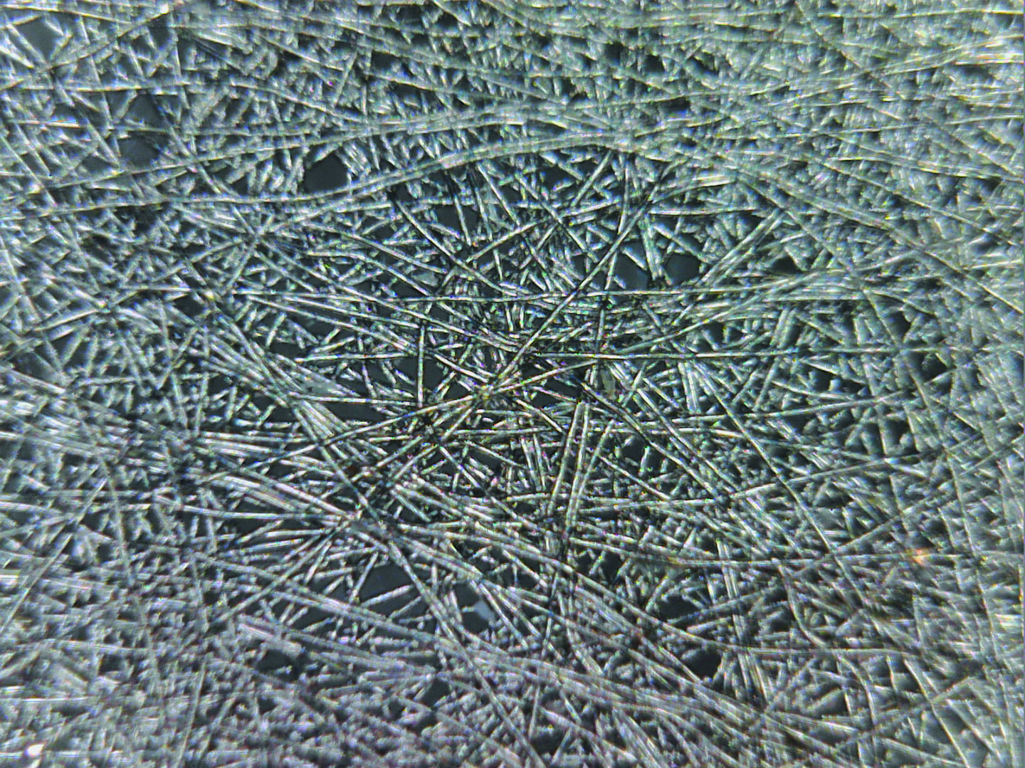 Figure 6. Close up of the shielding material S10.
The conductive fibers of the nonwoven form short-circuited meshes. The magnetic field is displaced from the metal of the meshes as the frequency increases (500 kHz to 200 MHz).
In the lower frequency range (< 1 MHz), the shielding material has no damping effect (see Figure 5). The induced voltage u2 and the inductance L12 are equal to the reference measurement in the empty chamber.
 Figure 7. Inductive penetration of shielding material in the lower frequency range without skin effect.
 Figure 8. Inductive penetration of shielding material with skin effect; magnetic field is forced into air-filled holes of the material.
From about 0.5 MHz, the inductance of the empty chamber remains constant at -169.8 dBH (3.23 nH).
Below 400 kHz the inductance seems to be increased. This is probably due to an increase of the voltage u2 caused by the influence of the electric field of the stripline 2.
First inductive effective principle: Starting at 0.5 MHz, the skin effect becomes noticeable in the metal parts of the shielding material (see Figure 7). The voltage u2 and the inductance L12 decrease progressively (see Figure 5). The induced voltage reaches its lowest value at 200 MHz. At this point, a new effective principle occurs that superposes the field shift in the metal of the fibers (Figure 8).
Second inductive effective principle: From 200 MHz, u2 increases linearly at 20 dB/dec and the inductance changes to a constant curve: -235.9 dBH (0.16 pH), (see Figure 5).
A magnetic field component of F2 penetrates through the air-filled holes of the shielding material. For lower frequencies this magnetic field component was weaker than the one penetrating the metal of the shielding material. Finally, as the frequency continues to increase, the whole field is displaced from the metal of the shielding material. The magnetic field now passes only through the air-filled holes of the shielding material (see Figure 8). The propagation path of the magnetic field lines no longer changes with increasing frequency. The inductance thus remains constant. The effect of the inductance L12 can be extrapolated further for higher frequencies.
The coupling inductance L12 of the shielding material is a material parameter which can be specified as specific line inductance L'12 [pH/cm].
Comparison of Shielding Materials
The inductive shield penetration was measured on six shielding materials and is shown in Figure 9.
 Figure 9. Magnetic shielding properties of six shielding materials with inductive coupling.
Above about 2 MHz, a good shielding effect can be seen for three materials (S10, S2 and 02). For three other materials (01, 03 and 04), the shielding effect was not present or weak up to 1.5 GHz!
The shielding effect of the materials varies greatly. It varies between ineffective and effective. The frequency ranges of the different effective principles shift slightly depending on the material.
Shielding material 04 has no magnetic shielding effect, it behaves like air (empty measurement chamber). Shielding material 03 achieves a magnetic field attenuation of only 3 dB at 1 GHz, while shielding material 1 achieves 12 dB.
The shielding materials 02, S2 and S10 are effective and show the frequency-dependent areas of the two effective principles. In the first range up to 200 MHz, the shielding material acts by field displacement through the holes of the meshes. In the second range >200 MHz, the effect is defined by the size of the metal-free holes in the meshes and their ohmic resistance (40 ... 65 dB attenuation). The structure of the shielding material determines the effect in both ranges.
The coupling inductance L12 of the shielding material is a material parameter that describes the penetration of the shielding material. It can be normalized to a 10 mm line current. The magnetic field attenuation is the distance in dB to the measurement without the shielding material (reference measurement). It can be calculated with L12-material [dBH] - L12-blank [dBH].
Concerning the design design, the quality of magnetic field shielding depends on the size of the holes in the meshes and their cross section and conductivity.
The measurement results in Figure 9 clearly show the effect of shielding materials against magnetic field. This provides an benefit for the application and development of shielding materials. During the development of the shielding material, it is important to constructively influence the two inductive effective principles.
With this measurement system, the user is able to select the appropriate shielding material for his application.