
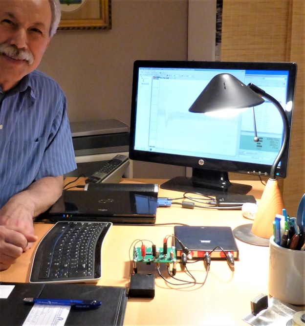
Istvan Novak: “From my very young age I always have had the luxury to have a lab at home or have access to a lab at work, mostly both. Having grown up in a big city, early on I got used to making the best of the available space; in my various homes the lab space was usually small and/or scattered around the home. Now I have my own office room in the house, but no dedicated ‘lab room.’ The lab area is scattered across three desktops and different storage areas. The actual instrumentation that I want to use depends on the project on hand; the instruments for each project are assembled temporarily. As such, there is no permanent look of my lab; these photos give a sampling of the various setups and typical instruments I have.
“The collection of instruments has been assembled over many years: I bought some of them new from their manufacturer or on Amazon, bought some of them used on E-bay, obtained some of them as donations. Some other pieces are hand-made circuits for projects that later I found useful enough to keep as part of the lab. And there are several temporary pieces that I get from companies and friends for certain projects or just to try out and give an assessment.
“The picture below shows my TiePie HS3 USB-powered oscilloscope while I am checking out one of my favorite demos that I show in my power integrity training courses, featuring a switching-mode regulators donated by its vendor. The oscilloscope has two input channels with 100Ms/s digitizers up to 16-bit nominal resolution (at lower sampling speed), plus an arbitrary waveform generator up to 10MHz repetition frequency.“
Some more images of Istvan’s lab:
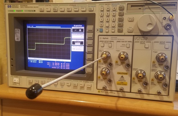
An old Hewlett-Packard mainframe with 20GHz TDR plug-in modules. This is the only permanent piece in the ‘lab’, sitting at the edge of the desk in my home office. I use it to check connectors and cables for possible wear and damage, also to sort cheap attenuators and other components that we can get by the bagful, to find the few decent parts.
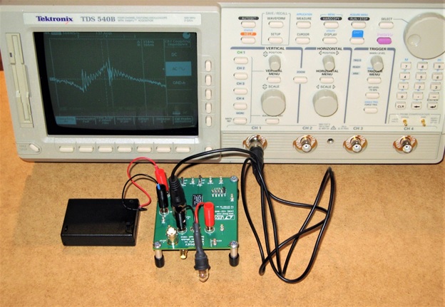
This is an even older Tektronix oscilloscope, a TDS 540B model with 2Gs/s sampling speed, 500MHz analog bandwidth. Though it has ‘only’ 8-bit digitizers, all four channels have a maximum sensitivity of 1 mV/div. One of the channels has a buffered output on the beck; it comes very handy when I need other instruments, too, to look at the same signal simultaneously.
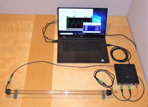
This image shows a newer TiePie oscilloscope model, HS5, with 500Ms/s sampling speed and 1uHz-40MHz arbitrary waveform generator, shown here as I prepare one of the transmission-line illustrations for my SI training courses.
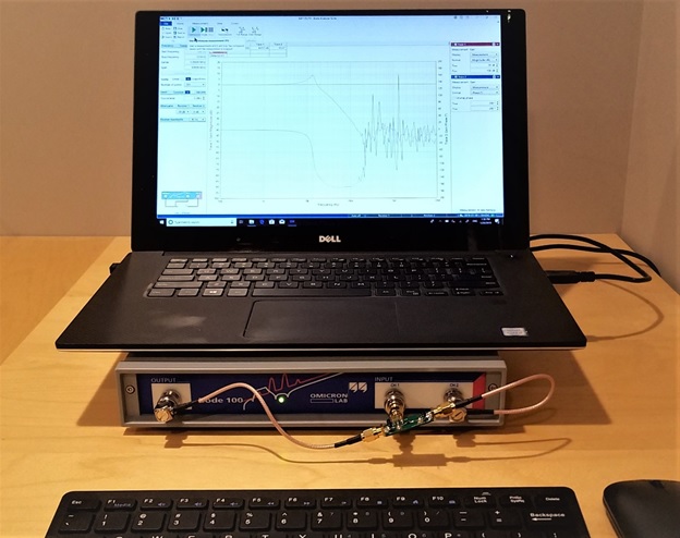
This was a temporary setup with an Omicron Bode 100 Frequency Response Analyzer, courtesy of Picotest, shown here in a setup measuring the transfer response of a PDN filter built on a little printed circuit board (attached to the middle BNC connector).

This is a setup to measure the control-loop stability of switching regulators. On the left is a HANMATEK HN305P 0-30V 0-5A bench power supply, on the right is a Keysight E5061B 5Hz – 3GHz network analyzer loaner, courtesy of Keysight. Just below the VNA screen, attached to the three BNC connectors is a home-made fixture to inject and sense the signals necessary for loop stability measurements. On the breadboard with a 9V battery connected is a home-made adjustable electronic load for up to a couple of amperes DC current.
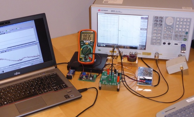
This is my favorite lab setup, illustrating the resilience of narrow-band frequency-domain measurements. On the right is a Keysight E5061B temporary loaner VNA, courtesy of Keysight. The device under test is the switching regulator demo board, the same that is shown in photo #3. It is powered from the small power supply in the perforated silver box. Three different tests are connected simultaneously to the switching regulator: output-impedance measurement with the S-parameter side of the VNA, gain-phase loop-stability measurement from the frequency-response analyzer side of the network analyzer, and a transient response test with the TiePie HS3 oscilloscope with its arbitrary waveform generator driving the built-in FET load of the switching regulator.

This image shows a current measurement setup with a temporary loaner E5061B network analyzer (courtesy of Keysight) with a Tektronix P6021 clamp-on current probe. The test signal is boosted with a Juntek DPA-2698 dual DC-10MHz power amplifier (this is the rectangular box -with striped top- connected to Port1 of the VNA), while the output signal of the current clamp is boosted with a Picotest J2180A-20 low-noise preamplifier loaner (courtesy of Picotest).
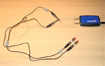
Finally, this one shows one of the permanent little VNAs in my lab that you can buy online: a miniVNA Pro two-port model from mini Radio Solutions. It covers the 100kHz – 200MHz frequency range. It is battery powered and can be controlled from a PC or phone, either through a USB cable or Bluetooth. Shown on the photo is a setup that can illustrate cable shield efficiency.
Istvan is a Principle Signal and Power Integrity Engineer at Samtec, working on advanced signal and power integrity designs and a member of the SIJ Editorial Advisory Board.
See Robert Haller's Lab on Next Page →