
What’s a hardware engineer to do? We’re stuck at home due to the COVID-19 pandemic, away from our normal labs and maybe not able to access some of the simulation tools we used to use regularly. As one of our colleagues once told us, “If I don’t touch a scope at least once a day my fingers twitch.”
If you are missing your engineering tools, or would like to build up your home lab, or want to finally work on that hobby electronics project you’ve put off for the last five years, or you want to introduce your kids to the thrill of measuring or simulating, now would be a good time to consider our list of free or very low-cost hardware and software simulation tools.
We are not advocating you replace your $100k, 20 GHz bandwidth scope with one of our recommended 35 MHz bandwidth scopes, but if you want a simple, easy to use, yet full featured scope, with limited bandwidth, it’s hard to beat the $100 to $400 price point of some of these low-cost multi-function scopes listed below.
Want to explore circuit simulation, or build your own circuit boards, but don’t want to commit major funds or spousal permission units (SPUs)? Now might be the ideal time to take these free tools for a test drive. They will never replace the professional level tools like Keysight’s ADS or Mentor’s Expedition, or Altium Designer, but they may be perfect if you want to design and build your first hobby board.
Here are our suggestions for low-cost but useful tools for home engineering projects. If you have a favorite low-cost tool not mentioned here, add it to the comments section.
Analog circuit simulators
An accountant has a calculator, and a hardware engineer has SPICE. If you can draw the circuit, a SPICE simulator can calculate the voltages and currents in the time or frequency domain on any node. It is an essential tool for every electrical engineer.
While there are a slew of tools with advanced features which you have to pay for, luckily, there are also a variety of free versions of SPICE. Your particular choice may be due to past experience, ease of use, or particular features. Note that if you need or use component models, there may be compatibility problems with your existing models with some versions of SPICE. If you need a particular vendor’s IC models, you may be limited to using the vendor’s version of SPICE.
The tool you like is a personal choice. What is important to one engineer may be a “who cares” to another. That’s what is great about options. One of our personal favorites is QUCS. Figure 1 is an example of a circuit model of a scope probe and the measured and simulated results from a fast edge source.

Fig. 1. An example of the circuit set up and simulated results from QUCS.
QUCS has the great combination of easy to use graphical interface, publication quality graphics output, and it is fast and computationally very stable. It is unique among the SPICE simulators in understanding S-parameters natively. This means you can important and export Touchstone [1] files to view and manipulate in the frequency domain. It has useful functions to manipulate S-parameters, like the unwrap function to turn the phase of an insertion loss into a time delay.
Unfortunately, it does not support S-parameter models in transient simulations and does not have a wide variety of models from the common ICs like SMPS devices, nor does it support lossy transmission lines. However, you can import some SPICE models, and they run.
Octave, a MATLAB clone, is natively integrated. This means you can write code in Octave to manipulate the simulated waveforms.
Here is our selection of free SPICE tools:
QUCS: Quite Universal Circuit Simulator: http://qucs.sourceforge.net/. This is a full featured tool that does all the normal SPICE simulations and specifically S-parameter simulation, reading, and exporting Touchstone files. It is our favorite.
LTSPICE: https://www.analog.com/en/design-center/design-tools-and-calculators/ltspice-simulator.html. This is a popular version of SPICE, created by Linear Tech (the LT part) and now supported by Analog Devices. There are extensive tutorial videos available on the ADI site to get you started. LTSPICE is widely used in many universities. If you use LT or ADI parts, this should be a first choice.
If you are a Python fan, there is a Python parsing library for LTPSICE: https://pypi.org/project/ltspice/
PSPICE student version: https://www.pspice.com/academic-user. This is one of the first SPICE versions available, originally supported by OrCAD, now Cadence. There are free versions and for-a-fee versions. One of us learned SPICE with PSPICE running on a DEC PDP-10, through a 1200 baud modem by typing in netlists in text (ask your parents about this).
PSPICE for TI: https://www.ti.com/tool/PSPICE-FOR-TI. Recently TI licensed PSPICE from Cadence and now offers many of its device models in PSPICE format.
TI also has its own version of SPICE, TINA (https://www.ti.com/tool/TINA-TI). Not the most stable version of SPICE, but many TI parts have TINA compatible models.
Honorable mention as online SPICE simulators: CircuitLab (http://www.circuitlab.com). This has a very clean, easy to use interface. Best of all, if you are learning circuit analysis, they have an online textbook with many interactive simulations demonstrating the basic and more complex circuit behaviors. And it’s all free.
Circuit or channel analysis tools
David Banas’ PyBERT is a Python-based serial communications link bit error ratio (BER) simulator. PyBERT accepts S-parameter files in Touchstone format as input and simulates the user-defined serial channel. Outputs include eye diagrams, bathtub curves, and jitter. PyBERT is available from Github for Linux, Mac OS, and Windows. Installation instructions can be found at https://github.com/capn-freako/PyBERT/wiki/instant_gratification.
Pete Pupalaikas’ SignalIntegrity is an open source Python-based tool suite for working with S-parameters. It includes an S-parameter viewer, tools for S-parameters for systems, de-embedding, virtual probing, linear simulation, a PRBS generator, and network analyzer calibration. SignalIntegrity can be found at https://github.com/TeledyneLeCroy/SignalIntegrity/releases for Linux and Windows.
Data display and analysis tools
There are other free software tools that will display S-parameters for you in the time or frequency domain and even build eye diagrams, all with a few mouse clicks. Keysight’s PLTS does it all, but it is not free. Mentor Graphics’ Touchstone editor is built into HyperLynx and is a quick and easy, full featured S-parameter viewer, but it is not free.
Teledyne LeCroy’s WavePulser interface, part of the Maui Studio download bundle, is free. You can download it from this link: https://teledynelecroy.com/mauistudio/ It will import any Touchstone file and display the S-parameters as single-ended or differential, in the time and frequency domains. Figure 2 is an example of a 4-port S-parameter file displayed in the frequency domain and the time domain.

Fig. 2. An example LeCroy’s WavePulser interface plotting an S-parameter file in the frequency domain and the time domain.
If you are familiar with MATLAB , you know what a rich programming environment this is. Just like Python, it is a programming language filled with many functions and routines from which to build complex programs. Unlike Python, there is no configuring, or installing libraries, just downloading, writing, and running. But, it is not free.
However, Octave: https://www.gnu.org/software/octave/index is a MATLAB “clone” that is “mostly” compatible with MATLAB, runs many MATLAB programs without modification and is free. If you have used MATLAB and want a free version, Octave is the one to consider. It is also built into QUCS and can do extensive post processing of QUCS circuit simulations.
As honorable mention in the category of display software tools, Rational Waves (http://rfexplorer.com/rationalwaves/) is a tool to interface with many software-defined radio (SDR) hardware tools to plot a measured spectrum. It is not free, but costs $79. If you have an SDR device, like HackerRF One (https://greatscottgadgets.com/hackrf/one/ ) or Analog Devices Pluto (https://www.analog.com/en/design-center/evaluation-hardware-and-software/evaluation-boards-kits/adalm-pluto.html#eb-overview ), Rational Waves provides the missing user interface to display the measured spectrum in typical formats like spectrum or waterfall, and it will even monitor specific bands.
Printed Circuit Board (PCB) Layout and layout analysis tools
The three top PCB layout tools, Cadence’s Allegro, Mentor’s Pads Pro, and Altium’s Altium Designer are powerful tools, but not free. If you are looking for free PCB layout tools, here are five recommended layout tools and three support tools for your PCB design activities:
-
Eagle free download (https://www.autodesk.com/products/eagle/free-download?plc=F360&term=1-YEAR&support=ADVANCED&quantity=1) is a limited version of the full featured tool designed for students and hobbyists. It is limited to two schematic sheets, boards with two signal layers (and multiple planes), and a total board area of 12.4 square in.
-
KiCAD (https://www.kicad.org/) is now the most popular free tool because it is open source and supported by many of the engineers at CERN and the Raspberry Pi Foundation. If you are looking for a free PCB schematic and layout tool that has legs and will probably grow in functionality, this is a good one to start with.
Many low-cost internet-based PCB fab shops offer a free PCB layout tool you can download and use. Here are three of the more popular tools from PCB fab shops:
-
PCB Artist (https://www.4pcb.com/free-pcb-layout-software/?matchtype=e&network=o&device=c&adposition=&keyword=pcb123&msclkid=a0b8e1c9219919d52d16be7d659f911f&utm_source=bing&utm_medium=cpc&utm_campaign=PCB%20Artist%20Software&utm_term=pcb123&utm_content=Competitors) from Advanced Circuits
-
PCB123 (https://www.sunstone.com/pcb123-lp) from Sunstone
-
Easy EDA (https://easyeda.com/?_ga=2.151123327.797758524.1605649641-346984517.1595289483) from JLCpcb.
Note that some of them, like PCB123, are tied to a specific fab shop, making it difficult to source your PCB somewhere else.
In addition to the layout tools, here are five other free tools, handy for a PCB designer.
-
Saturn PCB Design Toolkit (http://saturnpcb.com/pcb_toolkit/) is a rich collection of calculators for all things PCB. Figure 3 shows an example of the Saturn PCB calculator screen. If you want to know the maximum current you can put through a trace before it raises its temperature 10 degrees C, this tool implements the IPC2152 recommended equations.
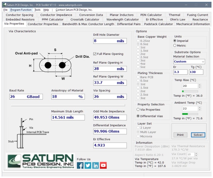
Fig. 3. Example of the Saturn PCB design calculator for a variety of useful PCB design estimates.
-
Gerbv (http://gerbv.geda-project.org/ ) is a simple to use Gerber file viewer. Just install it and import any Gerber file and you can view each of the layers in your board stack.
-
Cadence Allegro Free Viewer can be used to review and examine PCB layouts in .brd or Gerber format. It can be downloaded from https://www.cadence.com/en_US/home/tools/pcb-design-and-analysis/allegro-downloads-start.html
-
AppCAD for Windows, a free interconnect impedance calculator available for download from https://www.broadcom.com/appcad, was developed by Agilent Technologies (now Keysight), but is now owned by Avago Technologies. It includes calculators for estimating the impedance of interconnects with various geometries including microstrip and stripline traces, coplanar waveguides, and coaxial cable, from the materials properties and geometry. Unfortunately, it only works on single-ended geometries. A sample screen shot for a microstrip trace example is shown in Figure 4.
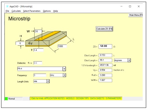
Fig. 4. AppCAD screen shot of microstrip trace example
Mentor Graphics’ HyperLynx Design Rule Checker (free for the first year) https://www.mentor.com/pcb/hyperlynx/electrical-rule-check/drc-editions, offers a limited version of their HyperLynx design rule checker for free. This tool checks your layout for potential signal and power integrity and electromagnetic compatibility (EMC) problems. Checks in the free version include traces crossing split planes, T-fork topology, and decoupling capacitor placement.
Digital Oscilloscopes and Signal Generators
An oscilloscope is like the Swiss Army knife of the lab. It is the most essential tool every electrical engineer needs. These four instruments have been selected because they also have at least one function generator built in, to make a multi-function instrument. Each of the low-cost USB based scopes in this list has at least two analog channels and one function generator. In Table 1 below, only the entry level scope version is listed.
Most of the entry level scopes in this price range are USB-attached units. In general, they have limited bandwidth. You won’t be able to debug your USB 3.0 5 Gbps signals, but you will be able to debug the signals in your solderless breadboard circuit or microcontroller project. For comparison, two benchtop scopes in this price range are included, with no function generator, but with a 200 MHz bandwidth.
|
Scope/vendor/URL |
Price, USD $ |
Analog BW |
BW of signal generator |
Power supplies |
Impedance analyzer |
Bode analyzer |
Logic Analyzer and decode |
|
Digilent AD2 https://store.digilentinc.com/analog-discovery-2-100msps-usb-oscilloscope-logic-analyzer-and-variable-power-supply/
|
$399 |
35 MHz |
12 MHz |
2, +/- 5 V |
yes |
yes |
16 channel, I2C, SPI, CAN, AVR, UART |
|
Red Pitaya STEM Lab 125-10
|
$235 |
40 MHz |
50 MHz |
no |
no |
yes |
no |
|
ADI ADALM2000
|
$150 |
25 MHz |
30 MHz |
2, +/- 5 V |
no |
yes |
16 channel, SPI, I2C, UART, Parallel |
|
Picotech https://www.picotech.com/oscilloscope/2000/picoscope-2000-overview
|
$140 |
10 MHz |
100 kHz |
no |
no |
no |
no |
|
Siglent SDS1202 |
$379 |
200 MHz |
no |
no |
no |
no |
no |
|
Rigol DS1202
|
$370 |
200 MHz |
no |
no |
no |
no |
no |
Table 1. A sample listing of low-cost oscilloscopes
Honorable mention: In addition to a scope and function generator, it never hurts to have a very vast square wave source. Surprisingly, there is a simple 40 psec rise time, 10 MHz square wave source, for USD $50 available from Leo Bodnar Electronics (https://www.leobodnar.com/shop/) in the UK. It is powered with a USB port. Figure 5 is an example of this source with a BNC connector. Leo Bodnar said this source generator board took him 12 different circuit board iterations to get right. We get to benefit from his engineering effort.
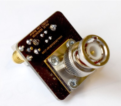
Fig. 5. The 40 psec rise time source from Leo Bodnar Electronics with BNC connector.
Vector Network Analyzers
Network analyzers are notoriously expensive. A 4-channel, 40 GHz VNA will cost from $50k to $250k. What can you expect for under $1k? Quite a bit, it turns out, as long as you don't need a bandwidth above 3 GHz. If you want to dip your toe into S-parameter measurements, these are low-cost entry points.