Data usage is increasing every year, and the communications industry is working diligently to support the increased demand. This article discusses why we need more data, what data center physical layer architecture changes are needed to support higher data rates, and how connector manufacturers are improving designs to support higher data rate systems.
Why do we need faster data transfer?
Many people around the world are working and learning from home due to the pandemic, and the remote paradigm has increased internet usage [1], see Figure 1. Specifically, the data is used for video meetings, remote access to servers, large file transfers, online gaming, and social media.
Today, there are approximately 2.7 billion Facebook and 2.3 billion YouTube users, and in 2021 humanity will spend 420 million years on these social media platforms [2]. Cell phones will release this year with new capabilities such as 8k and 360° video, and this large data content will be shared on social media platforms and streamed live [3]. In 2020, average households used 350 GB of data per month and many were at or above 1TB, the data cap for most internet providers, and data usage will increase moving forward. (The breakdown of various data usages is shown in Table 1.) Figure 1| Average household usage of data over 10 years [1]
Table 1| Data usage in Gigabytes
|
Data Per Month |
Data Per Day |
Data Per Hour | |
|
1,000 |
33.3 |
1.4 |
|
|
750 |
25 |
1 |
|
|
500 |
16.7 |
0.7 |
|
|
250 |
8.3 |
0.3 |
|
The rise of 5 G brings many new technologies to life [2]. Precision agriculture [4] uses 5 G connected sensors, drones, and automated hardware to waste less and produce more. Autonomous vehicles communicate updates to data centers via 5 G every two feet when driving at highway speeds [5]. Drones using the 5 G network are being used to make deliveries. UPS has already teamed up with Verizon to receive certification for delivering vital healthcare supplies via drones [6], and says 5 G makes this possible. Finally, augmented reality with 5 G will enable us to shop from home like never before.
To fully enable 5 G and all its glorious by-products, we need an upgraded infrastructure, and this infrastructure will include 112 Gb/s transmission per differential pair. For data centers, the change will be to implement the IEEE 400GBASE-KR4 and 400GBASE-CR4 protocol into their servers and switches, respectively.
How do we meet the data demand?
Data centers and edge data centers need to transition to higher speed architectures to support the services discussed above. The current generation in most data center servers today is IEEE’s 100GBASE-CR4 and 100GBASE-KR4 described in IEEE 802.3 clause 92 and 94, respectively. These protocols, which released in 2014, use signal speeds of 25.78125 Gbaud with non-return to zero (NRZ) modulation.
The next move to 200GBASE-KR4 is happening today. This protocol operates at 26.5625 Gbaud with pulse amplitude modulation level 4 (PAM4) modulation. The rate of each symbol (BAUD) has not changed dramatically, but each symbol now carries two bits instead of one. That translates to less signal available for each bit, and with less signal, the system signal-to-noise ratio is decreased.
To illustrate the difference, let’s consider a 100GBASE-KR4 backplane. The S-parameters of such a backplane is shown in Figure 2.
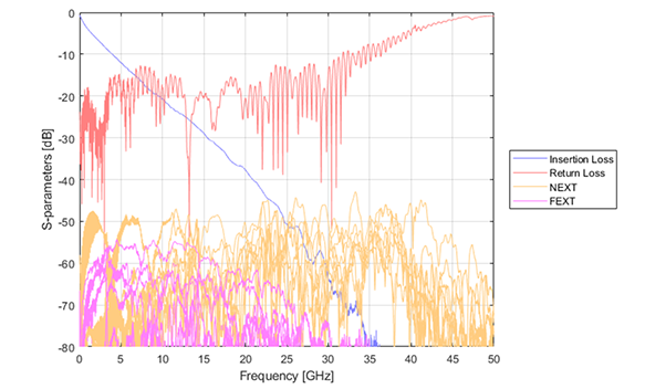
Figure 2|S-parameters of a 100GBASE-KR4 Backplane
This backplane has about 25 dB of insertion loss (blue line), 55 dB to 50 dB of near-end crosstalk (NEXT; orange lines) and 60 to 55 dB of far-end crosstalk (FEXT; magenta lines) at the 25.78125 Gbaud Nyquist frequency (12.89 GHz). This means the insertion loss to crosstalk ratio (ICR) is roughly 25 to 35 dB depending on the wiring pattern.
If we plot the eye diagram of the equalized channel only, without crosstalk, at 25.78125 Gbaud with NRZ modulation, we see a wide open eye with an eye height of approximately 40 millivolts and eye width of almost the entire unit interval (Figure 3). If we do the same thing at 26.5625 Gbaud, with PAM4 modulation, the situation is much worse (Figure 4). The eye height is approximately 13 millivolts and the eye width is only about 50 percent of the unit interval.
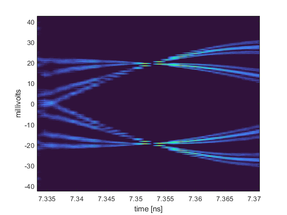
Figure 3|NRZ statistical eye pattern at 25.78125 Gb/s

Figure 4|PAM4 statistical eye pattern at 26.5625 Gbaud
Even though the signal level is significantly worse at 200GBASE-KR4 than 100GBASE-KR4, it is clear that doubling the bandwidth is still possible with the same interconnect system. That is great news for integrators and data center owners who are looking for an easy upgrade path.
Let’s see what happens when we consider 400GBASE-KR4, the next generation protocol for high-speed data centers, which operates at 53.125 Gbaud (26.56 GHz Nyquist Frequency). This protocol is synonymous to the OIF 112 G standards, and Figure 5 shows the statistical eye pattern.
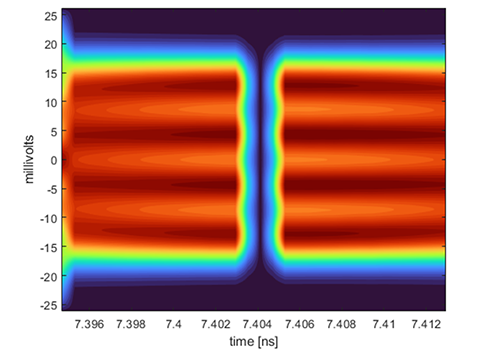
Figure 5|PAM4 statistical eye pattern of 53.125 Gbaud over a 100GBASE-KR4 backplane
The statistical eye has completely collapsed. Meaning, the current hardware does not work at 400GBASE-KR4. Another way to look at it is in terms of the industry standard metric of a working channel called channel operating margin (COM), in Figure 6. COM takes the electrical performance of the channel and adds the detriments of the IC all in one number, representing a signal-to-noise ratio in voltage decibels. In most cases, COM greater than 3 dB is passing the interoperability requirement.
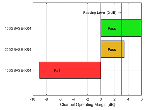
Figure 6|COM of various data rates over a 100GBASE-KR4 backplane
Just as the eye diagrams suggest, the backplane passes the 100GBASE-KR4 electrical requirement easily, passes the 200GBASE-KR4 requirement with less margin, and fails the 400GBASE-KR4 requirement by a great margin. It is time for an upgrade, but what do we need to do?
The first obvious issue is the high frequency needed for 400GBASE-KR4. The protocol is designed to accommodate 28 dB channels at 26.56 GHz. The current channel has around 52 dB of loss at that frequency, see Figure 7. Clearly, the backplane architecture needs to change. That can be done by making shorter channels, using better printed circuit board materials, or replacing the traditional backplanes with cabled solutions.
 Figure 7| Insertion loss of the 100GBASE-KR4 and proposed 400BASE-KR4 backplane with legacy connectors.
Let’s start by simply making the backplane have less loss. This is accomplished by making some concessions for trace length and using the best PCB material available. You can see the loss is now within the limitation of the 400GBASE-KR4 specification: 21 dB at 26.56 GHz (Figure 9). If we analyze this backplane with COM, it still fails (Figure 8), but why?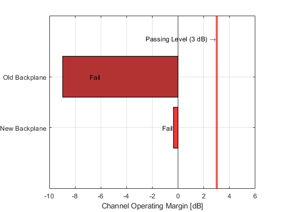
Figure 8|COM of the proposed 400GBASE-KR4 backplane with legacy connectors
The first step is to look at the S-parameters in Figure 9. The NEXT at 26.56 GHz is roughly 35 dB and the FEXT is around 45 dB. That makes the ICR approximately 15 dB for NEXT and 25 dB for FEXT. This suggests higher relative crosstalk is causing the failures.
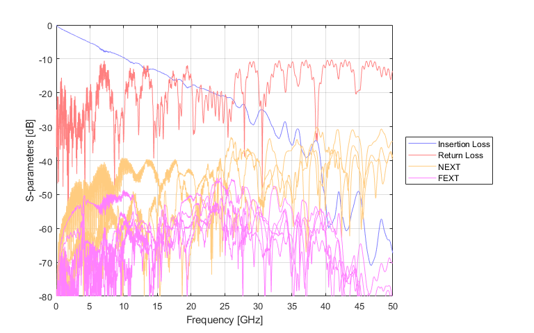
Figure 9|S-parameters of the proposed 400GBASE-KR4 backplane with legacy connectors
Digging deeper, Figure 10 shows the statistical signal and at the noise from crosstalk, reflections, and from the system, and we find there is simply too much noise in the system. To pass COM, the statistical signal-to-noise ratio needs to be higher than 1.41, and the new backplane has more noise than signal! Both reflections and crosstalk are adding similar levels of noise. However, the crosstalk seems to be primarily coming from NEXT, and FEXT is a relatively small.
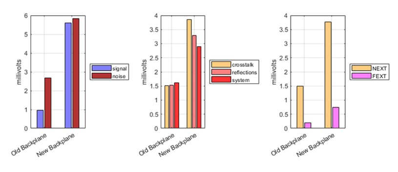
Figure 10|Breakdown of signal and noise levels in the 100GBASE-KR4 backplane and the proposed 400GBASE-KR4 backplane with legacy connectors
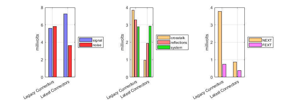
Figure 11|signal and noise levels of the proposed 400GBASE-KR4 backplane with legacy and latest generation connectors
If we change the connector system to something designed for 400GBASE-KR4 transmission and observe the noise sources again in Figure 11, we see the noise is reduced and the signal is slightly higher from removing radiation. As shown in Figure 12 and 13, this results in a working 400GBASE-KR4 channel!
From Figure 14, we see a working system at these frequencies needs to have insertion loss under 28 dB at 26.56 GHz and implement interconnect solutions with low reflections and near-end crosstalk.

Figure 12|COM of 400GBASE-KR4 backplane with legacy and latest generation connectors

Figure 13|PAM4 statistical eye pattern of 53.125 Gbaud over a 400GBASE-KR4 backplane
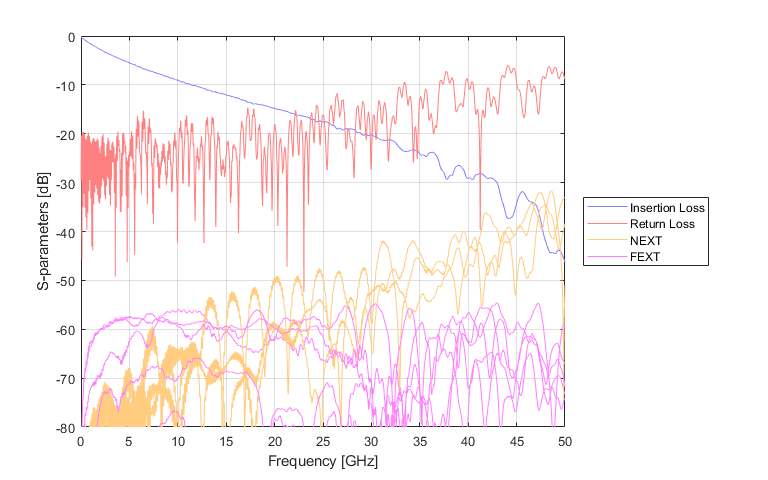
Figure 14|S-parameters of a 400GBASE-KR4 backplane
Conclusion
Connector manufacturers recognize the need for higher speed connectors and understand how to make connector solutions to enable these speeds. They have the tools and expertise to help get there, electrically and mechanically, as well as connectors needed for 112 G integration.
References:
[1] decisiondata.org, “REPORT: The Average Household’s Internet Data Usage Has Jumped 38x in 10 Years,” April 17th, 2020, accessed August 23rd, 2021.
[2] Eileen Brown, “We will spend 420 million years on social media in 2021”, February 18th, 2021. Accessed August 23rd, 2021.
[3] qualcomm.com, “5G The Fabric of Society”, June, 2018, Accessed August 23rd, 2021.
[4] Remi Schmaltz, “What is precision agriculture?”, April 24th, 2017, Accessed August 23rd, 2021.
[5] telekom.com, “5G network as foundation for autonomous driving” , Accessed August 23rd, 2021.