
Preamplifier with high common-mode rejection
The same dual operational amplifier can be used to create high common-mode rejection. In fact, if we don’t need high input impedance at the same time, using just one side of the dual operational amplifier is sufficient. The schematic is shown in Figure 8.

Figure 8. Preamplifier with high common-mode rejection.
The key to the high common-mode rejection is the balanced impedances in the positive and negative input paths. Precision 499-ohm resistors provide the good balance. The forward gain across a 50-ohm load is approximately unity, the input can handle common-mode voltages up to +- 3V DC. The common-mode input resistance, on the other hand, is just 499 Ohms, so this preamplifier is best used on Port 2 cables. The measured S parameters are shown in Figure 9. Note that the forward transfer parameter, S21 is -0.38 dB at low frequencies. This is due to the attenuation between the 50-ohm source impedance and the 1 kOhm one-sided input impedance. The construction is similar to the previous preamplifier, it will be shown in the next section.
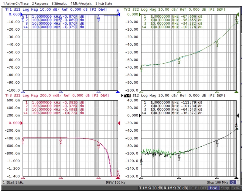
Figure 9. S parameters of the preamplifier shown in Figure 7.
Preamplifier with high input impedance and high common-mode rejection
If we want a universal preamplifier that can be used either on the Port 1 or on the Port 2 cable, we can cascade the two preamplifiers shown above. The schematic is shown in Figure 10. This amplifier has 6 dB forward gain between 50-ohm terminations, and, for this reason, its common-mode input voltage range is limited to +- 1.2 V DC. The measured S parameters are shown in Figure 11.
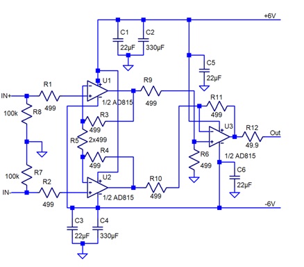
Figure10. Preamplifier with high common-mode rejection and high input impedance.
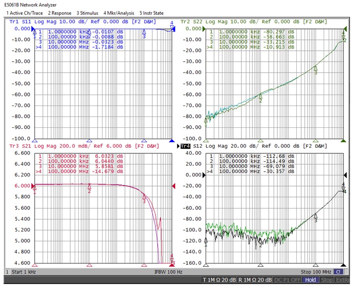
Figure 11. Measured S parameters of the preamplifier shown in Figure 10.
The second and third preamplifiers require a total of four operational amplifiers, so to utilize the unused half of the second dual operational amplifier in the preamplifier shown in Figure 10, the preamplifier shown in Figure 8 was built up on the same single proto board. The construction is shown in Figure 12.
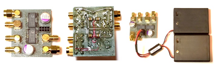
Figure 12. Construction of the preamplifiers shown in Figures 8 and 10.
Conclusions
Common-mode input impedance and common-mode rejection ratio are the two main parameters of preamplifiers that help to reduce the cable braid error in two-port shunt-through impedance measurement setups. When the preamplifier is used on the Port 1 cable, high common-mode input impedance is important. Common-mode rejection does not matter on the Port 1 cable. In fact, no common-mode rejection is preferred so that DC bias voltage from the source can propagate to the DUT when we need to measure DC bias dependence. When the preamplifier is on the Port 2 cable, common-mode rejection is the important parameter, and input impedance does not matter.
References
[1] “Measuring Milliohms and Picohenrys in Power Distribution Networks,” DesignCon 2000, available at http://www.electrical-integrity.com/Paper_download_files/DC00_MeasuringMiliohms.pdf
[2] “How the Braid Impedance of Instrumentation Cables Impact PI and SI Measurements,” DesignCon 2019, January 2019, Santa Clara, CA
[3] Accuracy Improvements of PDN Impedance Measurements in the Low to Middle Frequency Range, DesignCon 2010, February 1-4, 2010, Santa Clara, CA. Available online at www.electrical-integrity.com
[4] Picotest J2113A Semi-Floating Differential Amplifier - Ground Loop Breaker, https://www.picotest.com/products_J2113A.html