
I've been working in the field of electromagnetic compatibility (EMC) for nearly 35 years; first as an EMC engineer for Hewlett-Packard (later Agilent, now Keysight), then managing the product regulations test group, finally working up to a corporate leader and trainer in EMC. In 2008, I left the corporate world and started consulting and training; helping hundreds of client’s designs, troubleshoot, and test their products for EMC compliance. During this time, I helped troubleshoot thousands of EMC design issues for every industry sector; from military, aerospace, commercial, consumer, automotive and medical.
 Figure 1 - My current EMI troubleshooting kit with portable spectrum analyzer from AIM-TTi. (Not shown are the benchtop oscilloscope and spectrum analyzer.)
I was influenced by many notable figures in the EMC world. Among these was Henry Ott, who was one of my early mentors in the late 1980s. During one of his many in-house seminars, he suggested assembling an "EMC Crash Cart," which we eventually put together for use at HP. We took an HP "scope cart" and added a table top spectrum analyzer, along with an assortment of probes, cables and tools. This concept was based on his "Workbench EMC Troubleshooting" seminar.
I was also influenced by my friend and colleague, Doug Smith, who advocated building up an EMC troubleshooting kit into a roll-around Pelican equipment case. I thought this was a swell idea, so immediately purchased a Pelican 1514 roller case and started filling it up with useful tools (Figure 1).
The roller kit was especially handy, because we normally had 10 to 12 projects ongoing simultaneously at HP and I was able to roll the kit right up to an engineer's workbench and help them make measurements and perform some troubleshooting right there. No need for them to move the prototype product and support equipment over to our EMC test lab. This really helped speed up the process!
The purpose of this article is to help you gather the equipment, probes and other accessories to customize your own EMC troubleshooting kit. I hope you will find it useful whether you are an "internal EMC consultant" in a larger corporation, an engineer who “wears many hats” and occasionally is forced to deal with EMC compliance, or if you're consulting in the field of EMC for other companies. My hope is that the information within this article will help you become more efficient and offer a more professional appearance to your managers or clients, as the case may be.
Basic Essentials
Troubleshooting EMC issues can involve measurement in both the time and frequency domains. Thus, the two most important measuring instruments are an oscilloscope and spectrum analyzer.
Oscilloscopes - The best oscilloscopes for examining digital rise and fall times or circuit ringing might require bandwidths of 500 to 1000 MHz. But, for more casual troubleshooting, it's generally sufficient to just know a rise time is "fast" or that ringing is present. So, lower bandwidth scopes of 200 to 250 MHz may be sufficient.
Affordable brands to consider for benchtop use would be Tektronix, Keysight, Teledyne-LeCroy, Rigol, or Siglent. Sometimes a handheld scope would be more useful and B&K Precision, Fluke, and Siglent would be good brands to consider.
Spectrum Analyzers - Since the most EMC emissions problem areas occur between 9 kHz and 1 GHz, a modest spectrum analyzer of about 2 to 3 GHz upper frequency range is usually sufficient (Figure 2). Affordable examples might include the Teledyne LeCroy model T3SA3100 (9 kHz to 2.1 GHz), Siglent SSA 3000X-series (9 kHz to 3.2 GHz) or Rigol Technologies DSA800-series (9 kHz to 3.2 GHz). Many other manufacturers, such as Signal Hound, Tektronix, Rohde & Schwarz, and Keysight sell these. I'd recommend purchasing the tracking generator option as well for more advanced troubleshooting.

Figure 2 - A typical spectrum analyzer from Rigol Technologies, model DSA815TG, with tracking generator.
Near-Field Probes - Most engineers may be familiar with the small E-field or H-field probes that are used to detect small fields generated by digital circuits or circuit traces (Figure 3). While these can be easily made from thin flexible coax cables or semi-rigid coax, I find it more efficient to purchase a quality kit with probes in different sizes. Several companies make these kits; such as Beehive Electronics, Tekbox Digital Solutions, Rigol, or Siglent. Some of these kits also include a broadband preamplifier, which I'll discuss later on.

Figure 3 - A typical near-field probe kit from Tekbox Digital Solutions is often relabeled with other major brands. The kit includes an E-field probe, three sizes of H-field probes, and a 20 dB broadband preamplifier.
RF Current Probes - Several companies sell low-frequency current probes, mainly used for line frequencies or for frequencies as high as 20 MHz. However, what we generally need for EMC troubleshooting are current probes designed to measure RF currents out to at least 200 MHz or higher (Figure 4). Because radiating cables are often the primary cause of emissions failures, these probes can be clamped around I/O or power cables to measure the RF harmonic currents that produce radiated emissions.
Good choices of manufacturers include Tekbox Digital Solutions, Com-Power, or Fischer Custom Communications. The best current probes are hinged so they can be easily clamped around a cable. It does not take much RF current to fail the FCC Class B test; just 6 to 8 uA depending on frequency.
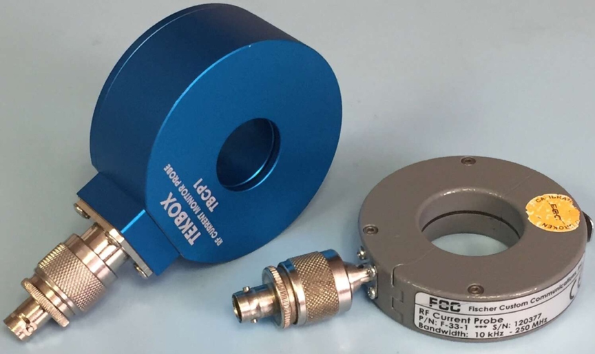
Figure 4 - Examples of RF current probes from Tekbox Digital Solutions and Fischer Custom Communications. These will measure microamps of RF current up to 200 to 250 MHz.
Antennas - A variety of different antenna types may be used successfully for troubleshooting radiated emissions; basically, anything that can be connected to the spectrum analyzer and observe the emissions may be used. It is important to note that for receiving emissions, the antenna does not need to be resonant at those frequencies.
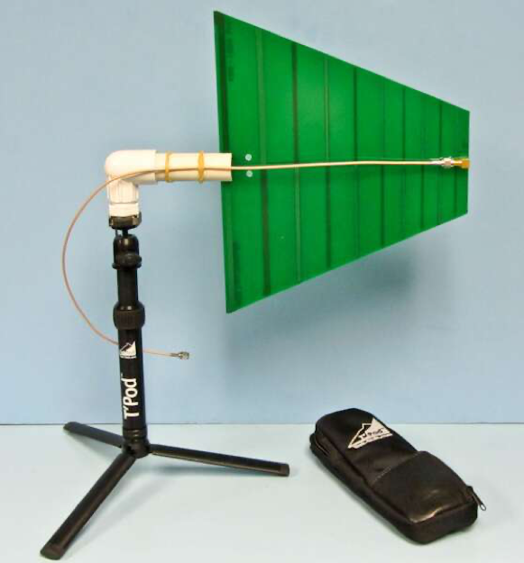
Figure 5 - An example of a low-cost troubleshooting antenna from Kent Electronics.
Most calibrated EMI antennas are broadband and resonant over the specified range, most commonly, 30 to 1000 MHz. They can cost upwards of $3 to $6k. Other types are designed to cover lower and higher frequencies. Having said that, I find one of the most useful antennas for troubleshooting is a simple PC board antenna designed by Kent Electronics (Figure 5). Their 400 to 1000 MHz log-periodic antenna is sensitive enough to cover harmonic frequencies in the 30 to 400 MHz band and costs just $33. I wrote an article describing a simple mount for use with a table top photographic tripod [1].
Broadband Preamplifiers - Some of the smaller near-field probes may require amplification to see a usable signal. Manufacturers would include Beehive Electronics, Com-Power, Rigol, Siglent, and Tekbox Digital Solutions (Figure 6).
 Figure 6 - An example of a broadband preamplifier from Tekbox. This one amplifies about 20 dB from 3 to 3000 MHz.
Coax Cables and Adapters - The most common coaxial patch cables I find are the common BNC-to-BNC in sizes of 6-inch, 12-inch and 24-inch lengths. Most RF test equipment uses "N" connectors, so N-to-BNC adapters are most useful. Some of the smaller RF modules, such as some RF synthesizers use SMA connectors, so you'll find a series of SMA coaxial cables and BNC-to-SMA adapters useful.
Ferrite Choke Kits - Ferrite chokes are especially useful for troubleshooting, because clamping one around a radiating cable will help "choke off" the RF currents causing the emissions. They come in different frequency ranges, depending on the ferrite material used; namely the low kHz to 10 MHz range and 10 MHz to 500 MHz ranges. Good manufacturers would include Fair-Rite, Würth Elektronik, TDK, Laird, Murata, and Leader Tech.
Common Mode Filter Design Kit - Würth Elektronik (WE) makes a terrific kit to help you design custom AC or DC line filters. Their model 744998 design kit includes several circuit boards with hole spacings and circuit pads to accommodate any of the dozens of different common mode chokes, capacitors, and resistors used to construct various topologies of filter designs. This can be obtained from your local WE rep or for just $190 from companies like Digikey.
EMI Gaskets - Any time two pieces of sheet metal are joined, there's the possibility of leakage and associated radiated emissions. When the usual fasteners are not enough, we often resort to various styles of EMI gasketing. This can include beryllium-copper finger stock, metal mesh gasketing, conductive fabrics and many others. Most manufacturers, such as Würth Elektronik, Laird, Leader Tech, and others will provide you a free sample kit.
Summary
These suggestions ought to get you started with a basic kit for troubleshooting the most frequent EMC test failure - radiated emissions. Reference [2] describes more detail on how to use these tools. For much more detailed information on other items to add to your kit, you might refer to my book [3].
Other blogs in this series will discuss conducted emissions testing and troubleshooting and various immunity testing and troubleshooting.
References
- Kent Electronics PC Board Antennas, https://www.edn.com/pc-board-log-periodic-antennas/
- EMI Troubleshooting - Step by Step, https://interferencetechnology.com/emi-troubleshooting-step-step/
- Create Your Own EMC Troubleshooting Kit (Volume 1), https://www.amazon.com/Create-Your-Own-EMC-Troubleshooting/dp/B08LGNFPC2/ref=sr_1_3