

Companies like Intel, Nvidia, AMD, Qualcomm, and Broadcom are putting more cores on a single die. Ampere is an excellent example where they have designed a cloud processor solution with 128 cores on a single die.
It is well known that to meet voltage ripple specifications, designers cannot control the current on these processing solutions. However, we can manage the impedance in our power distribution network (PDN) designs. The challenge is that these processor solutions require significant amounts of current, upwards of 1000A, so PDN targets continue to decrease to even lower levels. That means the necessary impedance targets are well below 100 uOhm and even below 32 uOhm.
Steve Sandler demonstrated the solution to this problem in a 2018 EDICON University session [1] on how to measure below 100 uOhm, demonstrating 22 uOhms in that session as well. Some key takeaways are minimizing the shield resistance in the cables used in the measurement setup, increasing the CMRR, and controlling the ground loop.
So, what if our impedance target is below 22 uOhm, or even below 10 uOhm? How do we measure that?
Before measuring below 10 uOhm, we first need a known device under test (DUT) to check our measurement setup after calibration.
Ok, so let’s get a 10 uOhm DUT to check our measurement setup. On second thought, where do I find a 10 uOhm DUT? The unfortunate answer is that we need to make it ourselves.
Figure 1 depicts the DUT that was created. However, when it was first made, it was not known precisely what the impedance of the copper on this PCB mount was. So how do we check this?  Figure 1. Depiction of 4.5 uOhm known DUT
As shown in Figure 2, by using an accurate power supply that sources 1A through the DUT and cables, the voltage drop measured by a 6.5-digit digital multimeter (DMM) is our impedance drop. Note the DC measurement uses the same connectors that the vector network analyzer (VNA) will measure through.

Figure 2. Measurement setup with power supply, DMM, PDN cables, and DUT
In Figure 3, a power supply is sourcing 1A through the DUT, using one connector, and we see a value of 5.6 uV at the other connector. Increasing the source current to 2A results in 10.1 uOhm. The value of the DUT was found by taking the difference between the 10.1 uOhm and the 5.6 uOhm results, equating to 4.5 uOhm. This method minimizes DMM offset errors. As a reminder, you should zero out your DMM before enabling the source current to your DUT.
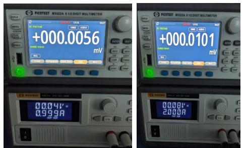
Figure 3. Measurement results with 1A and 2A current through the DUT
Now let’s circle back to how we measure below 10 uOhm with a VNA. This is where the dynamic range of your VNA becomes essential. The dynamic range is not just the difference between the analyzer receiver’s maximum input power and the minimum power; it’s the range from the maximum signal at a particular attenuator setting and the minimum measurable signal with the same setting. From 1 Hz to 1 kHz, the Bode 100 has a 115 dB of dynamic range.
What if our VNA does not have enough dynamic range?
This is where an external power amplifier can help. An external power amplifier can increase the input power to the DUT, which increases the signal-to-noise ratio (SNR) of your measurement setup. Steve Sandler demonstrated this in his EDICON University session [1], by showing that the only way to improve the SNR is to increase the source amplitude, unless the DUT is nearly noise-free, which is rarely the case.
As shown by the measurement setup with the copper short in Figure 4, we are using a Bode 100 with the OMICRON Lab B-AMP 12 power amplifier, the Picotest J2113A semi-floating differential amplifier, and two 0.25 meter PDN cables. The B-AMP 12 adds 12 dB to the signal source power, while the J2113A reduces the ground loop through its nearly 60 dB of CMRR.
The setup for the OPEN and LOAD calibration steps is the same as shown below in Figure 4, where the SHORT fixture is replaced with either an OPEN or a LOAD calibration fixture.
 Figure 4. Calibration setup with Bode 100, B-AMP 12, J2113A, and copper short
Figure 5 depicts the measurement setup with our now known 4.5 uOhm DUT after 2-port calibration. 
Figure 5. Measurement Setup with Bode 100, B-AMP 12, J2113A, and 4.5 uOhm DUT
After calibration, the 2-port shunt-through measurement results were captured with the Bode 100, B-AMP 12, J2113A, and PDN cable, as shown in Figure 6. The blue trace is the measured value of our copper short shown in Figure 4. This blue trace also represents the noise floor of our measurement setup. The red trace is the 4.5 uOhm known DUT. As shown in Figure 6, a value of 4.4 uOhm at 61 Hz is captured. This is within ~100 nOhm of our previous DC measurement setup, shown in Figure 2, which validates our calibration process.

Now that we have a known DUT, a measurement setup, and a calibration process, we are ready to execute measurements below 10 uOhm and follow the procedure shown in Figure 7.

Conclusion
This discussion demonstrated how to verify a known DUT. Having a known DUT for these low impedance measurements goes hand in hand with Eric Bogatin’s Rule #9: "Never perform a measurement or simulation without first anticipating the results you expect to see.” In addition, it was discussed how to use a VNA with external amplifiers to boost your SNR to measure a known DUT down to 4.5 uOhm to meet the impedance targets for the next-generation ASICs.
As a next step, since this measurement is clearly pushing the limit of this setup, we could try a VNA with a higher dynamic range, such as the Keysight E5061B. We could also use an external amplifier that provides even higher gain than the B-AMP 12. Lastly, we could redo our measurements after calibration with an even better short.
References
- S. M. Sandler, “How to measure ultra-low impedance (100uOhm and lower) PDNs,” EDI CON, October 2018.
- S. M. Sandler, “The 2-Port Shunt-Thru Measurement and the Inherent Ground Loop,” EDI CON, October 2018.
- Application Note – Ultra-low Impedance (20 micro-ohm) Measurement Using 2-Port Shunt-Through.
- OMICRON Lab Bode 100 VNA
- B-AMP 12 Amplifier
- Picotest J2113A Semi-Floating Differential Amplifier
- Picotest PDN Cables
- Ampere Altra Max 64-bit 128 Core ARM CPU Datasheet