

I do not know if there was a legitimate reason for this request, but I was once asked to determine the turns ratio of a power transformer inside a sealed, DC-DC converter module. In any case, there is not much usable information since the module is sealed, but we can apply a simple trick. Every switch generates magnetic and electric fields and some of this will be able to be captured in the air surrounding the module.
For this measurement I selected a small H-field probe and sniffed around the outside of the DC-DC module until I located a signal that looked like the primary switch. A picture of the measurement setup is shown in Figure 1.
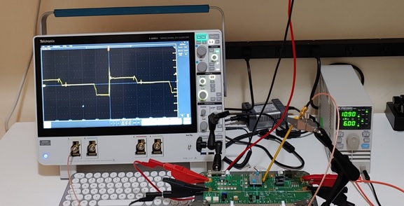
Figure 1 A small Beehive H-field probe was used to sniff around the outside of the module until the screen showed a measurement that looked like the primary switch waveform.
A lot of information can be obtained from this measurement. One thing we could determine is that the DC-DC converter is operating in discontinuous conduction mode. We can see this because the duty cycle changes with changes in load current. We can also tell that this is buck-boost derived, since the lower pedestal voltage is proportional to the input voltage while the step above it is fixed.
Using cursor voltage measurements, the two voltages are easily related. Here I used a ruler from the picture, just to show that the measurement can be accomplished even without the cursors, say from a picture of the screen.
Since the lower pedestal is related to the input voltage and the step above it is proportional to the output voltage, we can easily determine the turns ratio of the transformer.
The screen ruler measurements in Figure 2 show that if the first pedestal is the input voltage (48V) and the upper step is half as tall, the step is 24V and this is proportional to the output voltage (12V).
The turns ratio is easily calculated as Np/Ns=24/12 and so the turns ration is 2:1.

Figure 2 Using a near field probe, a location and direction are identified that provide a picture of the internal switching waveform. This screenshot provides all of the information needed to identify the transformer turns ratio.
Knowing that the converter is a discontinuous conduction mode, buck-boost derived converter, even more information can be obtained.
The relationships, shown in Figure 3, also allow the calculation of the primary inductance of the transformer.

Figure 3 Identifying the conduction mode and buck-boost nature of the DC-DC converter also allows the determination of the primary inductance and the peak switch current.
This measurement was originally presented at DesignCon 2021.