
CONCENTRICITY AND IMPEDANCE

Figure 2 Male center pins: 100 percent concentric (a), not concentric (b).
Mating two connectors to pass signals is the starting point for transferring data, accomplished through a pin and slotted receptacle. Published literature describes various mechanisms for mating connectors to 110 GHz. Often, what is not described is that designers must account for repeatable and proper concentricity as the dimensions for both the pin and slotted receptacle get smaller. The performance of a connector is only as good as how well it mates with another connector. Concentricity describes how balanced and centered the male or female mating receptacle is. Ideally, the concentricity would be 100 percent. Without sufficient concentricity, proper mating will be impossible and damage to the connector inevitable (see Figure 2).
Concentricity is a mechanical parameter, and decisions to address it will affect the connector’s electrical performance. One approach to ensuring proper concentricity is evaluating the subassembly. For 1 mm connectors, the assemblies are threaded and easily manufacturable. The thread assembly removes the need for very fine tolerances. Concentricity, in this case, is trivial. Because the 0.8 mm connector requires accuracy over a broader frequency range - theoretically up to 166 GHz - tolerances cannot be relaxed. Assembly tolerance error will determine whether a pin or receptacle will sit perfectly in the center of the connector, so assemblies must account for this. Press fitting the 0.8 mm parts is the alternative to threaded assembly. Press fitting the connector allows for shorter connectors and improves concentricity, since the distance from the reference plane to the support bead is shorter.
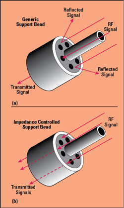
Figure 3 A generic support bead (a) reflects the RF signal, while an impedance controlled support bead (b) minimizes reflections.
After changing assemblies from threaded to press fit for proper mating, the next obstacle is controlling the impedance, choosing the right internal components to keep the impedance close to 50 Ω. The 0.8 mm connector, like most high frequency connectors, has a center conductor requiring support beads, which is an integral part of the design for both the connector and housing. Several types of beads can support a connector’s center conductor, with various impedance profiles and dielectric signatures. The support bead must provide mechanical stability and minimize reflections through the connector. Support bead design is critical to the overall electrical performance, the key parameter being the impedance. The center conductor support bead, in the middle of the connector and in the path of the RF signal, has holes to simulate air dielectric. To minimally influence the signal passing through it requires a controlled impedance with tight tolerances, to get the support bead impedance as close to 50 Ω as possible to avoid reflecting signals and degrading performance (see Figure 3).
In the initial phase of creating the 0.8 mm connector, we tested various beads and found that many of them, including glass, have impedance tolerances of 5 percent of the nominal value. For a metrology-grade connector, impedance control must be better than 5 percent. This bead should be transparent to the measurement. After much testing and research, a proprietary, high temperature bead was developed that offers the desired performance: good VSWR and low insertion loss, as well as ensuring mechanical stability and environmental ruggedness. Using a proprietary Anritsu bead enabled an 0.8 mm connector with a typical insertion loss of 0.5 dB at 145 GHz.
Another design consideration is whether the connector should be compatible with 1 mm connectors. By choice, the 0.8 mm connector is not compatible with the 1 mm connector, as damage will occur when mating them. This was addressed by adding a fine thread to the connector to prevent the 0.8 mm from mating with a 1 mm connector, also preventing the connector from becoming loose during operation.

Figure 4 Measured insertion loss (a) and phase (b) of an Anritsu 0.8 mm female-to-female adapter, from 100 MHz to 145 GHz.
TESTING AND PERFORMANCE
After much design and evaluation, the finished 0.8 mm connector has a typical insertion loss of 0.6 dB from low frequencies to 145 GHz. After achieving this performance in the connector, Anritsu applied the same technology to cables and adapters. An 0.8 mm female-to-female adapter, tested with a 145 GHz vector network analyzer (VNA), has less than 0.5 dB insertion loss and linear phase response (see Figure 4).

Figure 5 90 Gbps eye diagram of the Anritsu 0.8 mm female-to-female adapter.
To assess the time domain performance for applications using an 0.8 mm connector to carry a digital signal, Figure 5 shows the eye opening of the same Anritsu female-to-female adapter with a 90 Gbps data rate signal; Figure 6 shows a 90 Gbps PAM 4 signal, both measured with a VNA with non-return-to-zero and PAM 4 eye diagram options. Both figures show excellent performance with high speed digital signals.
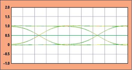
Figure 6 90 Gbps PAM 4 signal through the 0.8 mm female-to-female adapter.
AVAILABILITY
The 0.8 mm connector technology provides metrology-grade performance from DC to 145 GHz and is currently the only 0.8 mm connector on the market. Anritsu is integrating this platform in new components and test systems, such as screw-in sparkplug connectors, cables and test equipment. The 0.8 mm sparkplugs are pin and socket connectors covering DC to 145 GHz with 0.7 dB (typical) insertion loss. Anritsu has developed armored semi-rigid cables with 0.8 mm male-to-female connectors, available in 10 cm and 16 cm lengths. The cables have excellent insertion loss and return loss performance.
Anritsu test equipment with the 0.8 mm connector provides coaxial frequency coverage to 145 GHz. The VectorStar VNA with optional mmWave modules and 0.8 mm connectors covers from 70 kHz to 145 GHz with one sweep. An 0.8 mm calibration kit for the VectorStar VNA includes metrology-grade adapters and standards for the highest performance.n
References
- R. J. Collier and A. D. Skinner, “Microwave Measurements, Third Edition,” Stevenage: Institution of Engineering and Technology, 2007.
- B. Oldfield, “The Importance of Coax Connector Design Above 110 GHz,” Anritsu Co., 2007, https://dl.cdn-anritsu.com/ja-jp/test-measurement/reffiles/About-Anritsu/R_D/Technical/E-22/22_07.pdf.