
If you're taking power-rail measurements on a semiconductor die that is appropriately instrumented with sense lines and a direct connection to the die's core PDN, you're in pretty good shape. But what if that's not the case? If the die's I/O power rails are shared by the core power rails, here's a way to get your core power-rail measurements anyway.
Let's look at a schematic rendering of a typical, generic I/O. You'll find a CMOS driver (center left) that's fed by some signal-conditioning circuitry (not shown). The CMOS driver comprises P- and N-channel gates that are connected internally to the Vcc rail (at top, within chip boundary in red) and the Vss rail (at bottom, also within chip boundary in red), respectively. There is some amount of resistance in the on-die rails and some inductance in the leads from the die itself to the package. Outside the package boundary (in blue) are connections to the on-board power-delivery network (PDN).
When the I/O is set as an output-low, that means the N-channel is turned on. The green point, in Figure 1 is then connected to the Vss rail. If we measure that point relative to PCB ground, we're measuring the relative noise on Vss compared to the system-ground level on the PCB.
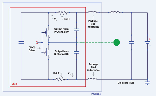
Figure 1: This schematic represents the I/O paths in typical, general-purpose I/Os
Likewise, if we have another I/O set as an output-high that means the P-channel gate is turned on and the N-channel gate is turned off. Now, the green point in Figure 1 is connected to the Vcc rail, and we can measure the relative noise on Vcc compared, again, to the system ground.
Thus, by using two different I/O that are dedicated as an output-high and an output-low as sense lines, we can measure the voltage noise on the low rail relative to the ground reference on the board, and we can do the same with the high rail. By doing so, we can get a pretty good idea of what the voltage noise is on the die without having the dedicated sense lines. If the I/O rail happens to be connected to the Vdd rail, measuring Vcc and Vss will give us valuable information about Vdd as well.
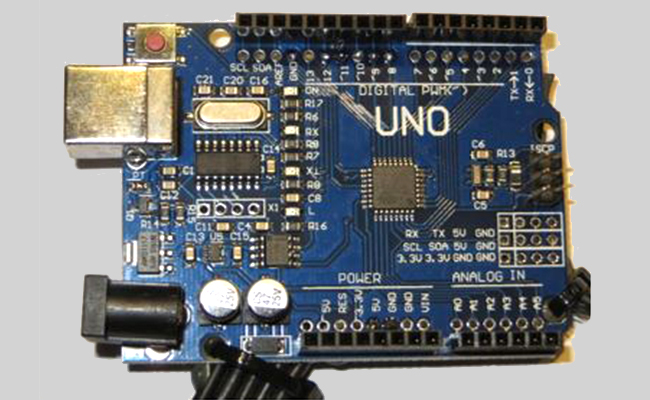
Figure 2: A simple microcontroller will serve as DUT for on-die power-line measurement examples
To make quality measurements in this fashion, we still must follow good design (and design-for-test) guidelines. The connection off the die must be a transmission line, which means a coaxial connection onto the rail probe.
Previously published version in the Teledyne LeCroy Test Happens Blog.