
If you missed the chance to attend the first EDI CON (Electronic Design Innovation Conference) in Boston last Aug, you missed the first conference to bring together industry participants across the spectrum of rf, microwave, wireless and high speed digital applications of signal integrity, power integrity and EMI. Rarely are these divergent, yet related fields addressed under one roof.

Figure 1. A lively group attending the tradeshow at EDI CON 2016.
While there were a number of occasions for me to pick up new insights, I wanted to share six events in particular.
Two Technical presentations of note
In the technical presentations, I listened to back to back presentations from Bert Simonovich, an SI Journal Editorial Advisory Board member, and Al Horn, an Associate Research Fellow at Rogers Corp. Both of their themes centered around conductor loss in circuit board interconnects.
With the introduction of ultra-low loss laminates, conductor loss is the dominant limitation to pushing the envelop of ever higher data rates. And, the surface roughness of the copper can more than double the conductor loss over smooth copper. Bert’s talk reviewed a spin on the Huray Snowball model for surface roughness. In Prof Huray’s model, the surface of the copper is modeled as composed of hillocks composed of piles of small copper balls, or nodules.
The extra loss from these nodules arises from coupling of the tangential component of the magnetic field vectors that propagate along the surface of the copper. Induced magnetic fields in the copper balls propagate into the copper and suck out power from the propagating signal.
To accurately account for this coupling, we need to know the size of the balls and the shape of the hillocks. Bert developed a simple model, based on cannon ball stacking, to relate the hillock size and the ball size. This way, there is only one parameter, the diameter of the nodules, which affects the roughness loss calculation.
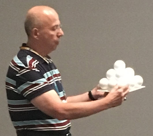
Figure 2. Bert Simonovich and his cannon ball stack of copper nodules.
What Bert was able to show is that three different stacking geometries of cannon balls in piles give exactly the same loss. This means there is really only one parameter needed to predict the roughness losses. And, this parameter can be derived from a simple roughness metric of the copper surface. This enables accurate prediction of the contribution of copper roughness.
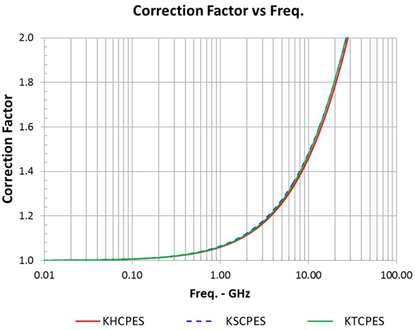
Figure 3. Loss correction factor calculated for three different stackings of cannon balls, all showing just about the same impact on loss.
Al Horn’s talk reviewed many examples of the measured loss in low loss laminates with different roughness copper. He showed that both the Hall-Huray model and the numerical model built into Sonnet Software predict the losses from roughness very well.
But, the startling conclusion was that it is possible to achieve nearly perfect smooth copper loss with some types of copper foils. “Rolled foil loss values match smooth copper values out to 110 GHz. It’s the nodulation treatment that increases loss on copper surface not the surface roughness of the copper itself.”
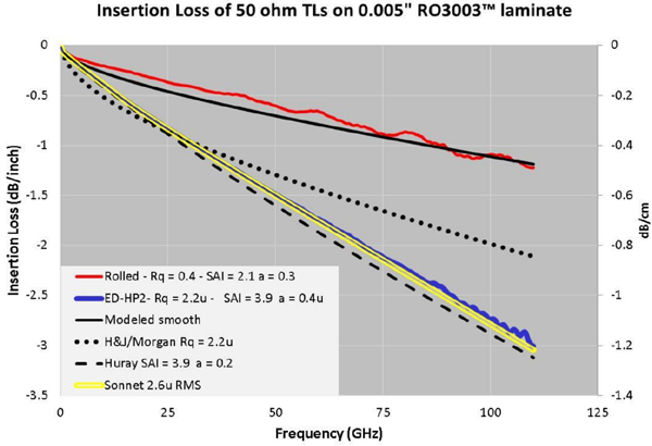
Figure 4. Measured loss of various types of copper foil and the simulated predictions. Note the red trace for the measured loss of rolled copper, has exactly the same loss predicted for smooth copper, the black line.
While modeling accuracy is important to predict performance, achieving performance is even more important. And performance is about selecting the right copper foil. The key is finding the balance between a slight nodulation treatment to rolled copper for acceptable adhesion while not adding additional loss. Rogers is pursuing ultra-low loss laminate materials with rolled copper foils using the minimum nodulation treatment for acceptable adhesion. This may end up being the optimum laminate for high-speed interconnects.
Most interesting Frequency Matters Theater Presentations
I don’t know much about microwave ovens, other than they operate at about 2.48 GHz. It has nothing to do with the resonance of water, but to the unlicensed ISM (industrial, scientific, medical) FCC band, 2.400 GHz to 2.4835 GHz.
I learned from Dr. Klaus Werner of the RF Energy Alliance, a very important role solid state microwave power amplifiers might play in the microwave oven industry.
Currently, microwave ovens are powered by magnetrons. These are resonant cavity high power microwave generators. Their frequency is set by the physical parameters of the magnetron and frequency tuning is not practical for ovens. When driving a microwave oven, transferring the most energy into the oven means the return loss, S11, should be a small value, below -15 dB even. The precise frequency of the magnetron is usually set to the frequency for the lowest return loss.
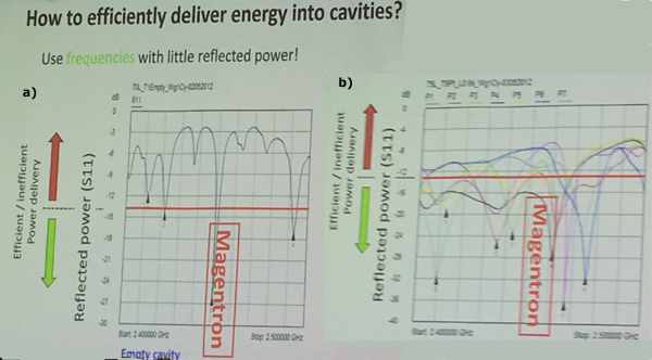
Figure 5. Left, return loss of a microwave oven showing the optimum frequency setting for a magnetron. Right, return loss for the same oven when loaded with food. The optimum frequency shifts with load.
However, as soon as the oven is loaded, the resonant frequency shifts and the magnetron is not so efficient anymore. A more efficient way of driving microwave ovens is using solid state synthesizers and power amplifiers so the frequency can be dynamically tuned to deliver the most energy into the oven. Klaus suggests this may become a killer app for low cost, high power solid state microwave devices.
Coolest Booths
In walking the show floor, two booths in particular stood out as pretty cool. The first was from Lighthouse Technical Sales, a manufacture’s rep for many rf and microwave components. The owner of the company, a model railroad fan, brought a full scale model railroad set decked out as a military camp with a train loaded for bear. I was not the only one standing around for minutes watching the train go round and round, admiring the exquisite detail.
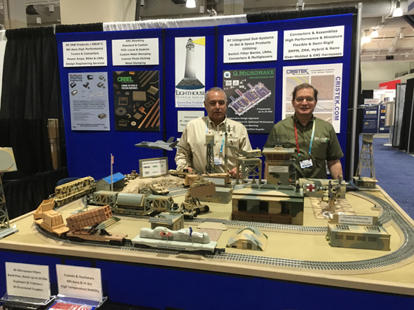
Figure 6. A fully functional model train supplying an advanced forward base with modern weapons systems. Larry Knight, president of Lighthouse Technical sales is on the right.
I am an engineer. Flashing lights and microscope images of detailed electronic components are to me like a fluttering bird to a cat. (That’s actually a line out of my novel, Shadow Engineer.) The GigaTest Labs booth, set up by my long time buddy, Harry Christie, showed one of their GTL4040, large probe station probing a board in three dimensions. Two pairs of 26 GHz probes made contact to a mezzanine board assembly, configured as it is used in its final application. This enabled the measurement of the entire channel from BGA pad to BGA pad from one board to the other.
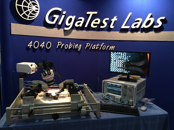
Figure 7. Four port probing a circuit board in 3 dimensions to 26 GHz.
I am the first to admit that I am not an rf expert. I only pay peripheral attention to the latest in antennas, but do follow the exploding field of Internet of Things (IoT). One feature of these products is the requirement to have a wireless interface, either as zigbee, wifi or even celluar. One of the challenges for wireless applications is small form factor. If you are designing an antenna for 900 MHz, for example, Maxwell’s Equations dictate that it must be about three inches long.
How do you fold a three-inch-long antenna in a tiny package and still have it efficient? With fractals. The coolest technology I saw was from Fractal Antenna Systems. They’ve leveraged fractal folding patterns in their antennas to pack a longer length in a smaller area. And they look really cool.
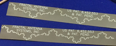
Figure 8. Example of a linear fractal pattern used for some antenna systems to pack more path length into a smaller area.
Coolest Demo
Nathan Cohen, founder and president of Fractal Antennas Systems, gave the coolest demo of an invisibility cloak. It wasn’t quite the Harry Potter invisibility cloak, but more like the Wright Brother’s version of a Space Shuttle.
As his company’s name indicates, Nathan is enamored with fractal shaped antennas. He has found that when the spacing between adjacent legs is less than a ¼ wave, he creates a highly coupled system, but which couples through evanescent waves, rather than propagating waves.
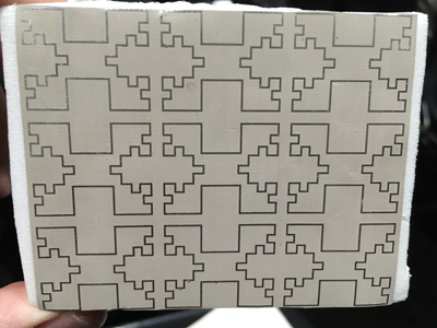
Figure 9. Close up of the fractal antenna pattern with tight coupling between adjacent legs creating evanescent coupling, the essences of an invisibility cloak.
When large sheets of evanescently coupled antennas are rolled into a cylinder, it seems as though an incident plane wave to the cylinder couples into the sheet and propagates along the surface of the sheet, as an evanescent wave. It follows the contours of the sheet to the antipodal position where it converts back into a traveling planar wave. This effectively bends most of the incident wave around the cylinder, shielding whatever is inside, cloaking it from the radar probe.
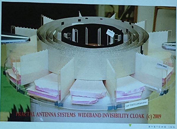
Figure 10. Cloaking objects inside the cylinders constructed of sheets of fractal antennas.
He demonstrated this live before the audience. Two antennas, separated by about three meters, were driven by the ports of a VNA so we could see the insertion loss in real time. When a sheet of aluminum foil was placed between the antennas, of course, the beam was blocked and the insertion loss dropped by more than 30 dB.
But when this foil was wrapped inside a closed sheet of his fractal antenna, the insertion loss dropped by only 5-10 dB. One of the secrets to success, Nathan said, was how the edges of the antenna sheet come together around the circumference.
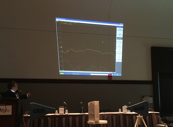
Figure 11. Nathan Cohen demonstrating an invisibility cloak for an aluminum foil wall inside sheets of fractal antennas.
Nathan was the first to admit he is not sure of the precise mechanism for cloaking and has not been able to model this effect with a traditional 3D full wave field solver, but he did a masterful job of demonstrating this effect.
Don’t miss the next EDI CON 2017.