

In exploring source options to demonstrate ringing from reflections in transmission lines, I came across a simple driver that works exceptionally well. Diving deeper lead me to finally understand debouncing circuits, completely unrelated to the reflection-effects that got me started down this path.
Measuring power rails has a unique set of challenges, different than measuring signal lines. One of the differences is that the source impedance of a power rail can be very low, often less than 1 Ohm. This means that if you use a coax cable to connect to the power rail, with the scope input impedance set to 1 Meg, so it does not load the rail, you will see reflections in the cable from any transient signal.
The reflections introduce an artifact and degrade the signal quality. Figure 1 shows the diagram of a low impedance source, transmission line, and scope input at 1 Meg, and an example of the resulting ringing noise at the scope from a low impedance gate driver.

Figure 1. Circuit illustrating low impedance source and high impedance scope input. Insert is the measured signal at the scope, using a Teledyne LeCroy HDO 8108 1 GHz, 12-bit scope.
A Novel Low Impedance Source
I wanted a lower source impedance driver to show the longer ringing time from the lower source impedance of a power rail. The problem is that fast drivers are designed with a source impedance of 50 Ohms, precisely to avoid this problem even when driving some other load impedance. Using a 50 Ohm source impedance means any reflections from the far end load would be terminated when they reflect from the load and come back and hit the source.
In my quest to find a low impedance, fast source, I decided to use a relay switch that would connect any voltage regulator module (VRM) source to a coax cable and turn it on quickly. The question was how fast would the relay launch the low source impedance voltage into the cable?
I used a simple 5 V relay driven by a simple pulse train from a microcontroller. The relay connected a 5 V SMPS into an RG174 cable and then into the scope, as illustrated in Figure 2.
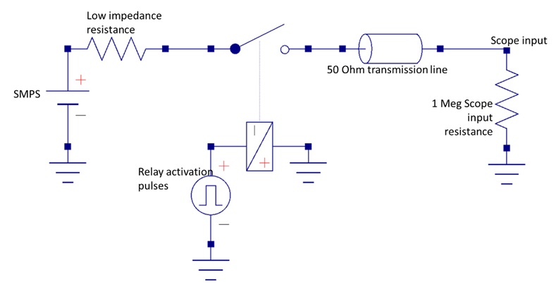
Figure 2. The set up I used to measure the signal launched into the coax from the SMPS switched through a relay.
With the scope input impedance set to 1 Meg Ohms, the received signal from the relay showed exactly the ringing I expected to see. The total length of the RG174 cable was about 5 feet long, making the round-trip time delay about 18 nsec and the estimated period of the ringing about 36 nsec. Figure 3 shows the measured ringing with 1 Meg input impedance on the scope. I was pleasantly surprised to see the rise time of the signal was shorter than about 4 nsec. This was probably limited by the large loop inductance of the connection I made into the switch.
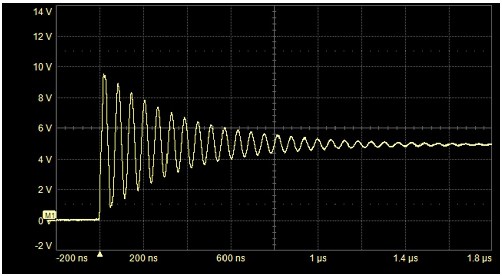
Figure 3. Measured voltage at the 1 Meg input to the scope, with the SMPS switching into the coax cable. Note the very long ringing time from the low source resistance.
The relay switch worked perfectly to demonstrate ringing, with a surprisingly fast turn on time at first contact and a suitably long ringing time.
A best measurement practice to eliminate this sort of ringing is to use a 50 Ohm termination in the scope. Once the first signal hits the 50 Ohms of the scope input receiver, there are no reflections and the signal turns into heat.
But when measuring a voltage with a 50 Ohm termination, it’s important to NEVER exceed 5 V rms voltage or the power dissipation in the scope’s terminating resistor may be enough to thermally damage the resistor. This is a potential danger with any scope.
Enter Mechanical Bounces
While playing around with the signal from the relay, I noticed the huge amount of bouncing in this relay. When I zoomed out on the signal from the relay, I saw each individual bounce of the relay. Figure 4 shows the amount of bouncing that happens in this specific relay. After the first contact, the switch bounces open, then the relay magnetic field brings them back in closure, then it bounces, until the bounce energy is dissipated and the magnetic field of the relay is able to keep the switch leads in steady contact. This is typical of any mechanical switch. They all bounce.
 Figure 4. Measured voltage into scope with a 1 Meg input after switch is closed. Note the many bounces of the switch opening and closing until it stays closed after about 1.2 msec. Note also the ringing on each bounce momentary contact.
As a general rule, the bouncing time depends on the mechanical properties of the relay but generally never lasts longer than about 2 msec. This is compared to the ringing from the reflections at the ends that rarely last longer than 2 usec.
Bouncing is a problem when a mechanical switch is used in some digital applications, especially as a reset. If the switch is used to pull an input low or high, and the digital input is read faster than every 1 msec, the input may reset multiple times. If the switch drives an interrupt, the interrupt may be triggered multiple times when it was meant to be triggered only once. This is why it’s important to clean up the signal from any mechanical switch. This is called debouncing.
If we have the option, we can always debounce in software. We simply read the input until we see it pulled high or pulled low, do what we need to do, but wait 1 msec before the input is watched again. By then, all the bouncing has happened, and the switch is in steady contact.
We can do this in hardware by adding an appropriate RC filter. But, this requires placing the R and the C in the appropriate places.
A Debounce Capacitor
If we are pulling the input low with a switch, it has to first be pulled high. If done externally, we usually use about a 20k resistor to Vcc. To debounce the switch, we place a capacitor across the switch, as shown in Figure 5. Usually, with the switch open, the capacitor is fully charged, the input is HIGH and stable.
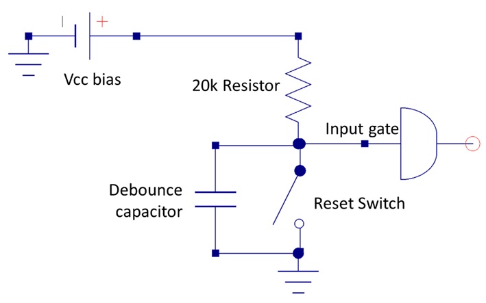
Figure 5. Typical reset switch circuit.
When the switch closes, the capacitor is discharged in the first contact with a time constant that is very short, since the switch has such a low resistance. Some debounce circuits suggest putting a resistor in series with the capacitor and switch to limit the discharge current through the capacitor and increase the discharge time. It’s a question of how quickly you want the switch to signify a close. This circuit shows the input pin a closed signal on the very first contact.
When the switch opens on the first bounce, the capacitor, still low, begins to charge with the RC time constant of the 20k resistor and the capacitor.
Between each bounce, if the RC time constant is long enough, the capacitor does not have time to charge up very much and it keeps the pin low. We want the RC time constant to be long compared to the time between bounces, but short compared to the time we want to wait between resets. A 2 msec time constant is a good compromise.
With a 20k pull up resistor, the capacitor should be 0.1 uF for a 2 msec time constant. The debounce capacitor value matters. If the time constant is too short, there may be time between bounces for the voltage to charge up to a value that could trigger another reset. If the debounce capacitor is too large, the reset switch may not be able to respond fast enough to consecutive triggers.
Figure 6 shows the voltage at the pin when the switch closes, with no debounce capacitor and with one that is 0.01 uF and 0.1 uF. Note that the 0.01 uF debounce capacitor is not large enough to keep the input pin voltage low during the first few bounces.
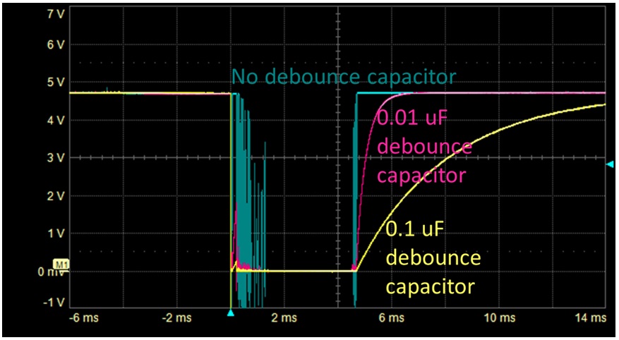 Figure 6. Measured voltage at an input pin under three cases of debounce capacitor values. Note the 0.01 uF cap with a 0.2 msec time constant is not large enough. The initial close time is the same, very short time in each case. The input pins sees the closure on the very first contact.
A similar circuit can be set up in the case of a pull-down resistor where the switch pulls the pin HIGH.
In some reference designs I’ve seen, a debounce capacitor is placed across the switch without the pull up or pull-down resistor. Just adding a capacitor across the switch won’t do anything for the bounces if the capacitor can charge back up in between the first few bounces.
As a best design practice for the capacitor to debounce the switch, the capacitor has to be part of an RC circuit. The switch discharges the capacitor in the first few microseconds of contact and keeps it low between bounces. The resistor has to be there to slowly charge the capacitor back up after the switch is opened by the initial bounce.
While a switch is a mechanical device, it makes initial contact to connect an output to another circuit in just a few nsec. But, its subsequent mechanical actions must be compensated to prevent the bounces creating an artifact that could last more than 2 msec.