
The Spring semester is starting at the University of Colorado, Boulder and the next batch of graduate students are taking my signal integrity course. To encourage students to be on time, I use a carrot and a stick. The carrot is a joke of the day and the stick is a pop quiz that happens as soon as class starts.
The jokes of the day are typically corny ones, but relevant to engineers. Like, the one about the Priest, the doctor and the engineer who are out golfing and encounter a really slow group ahead of them. The engineer asks one of the golf course officials why the other group is so slow. He says they are a group of firemen who helped save the clubhouse when it almost burned down. But, they lost their sight fighting the fire and the club allows them to play for free.
The Priest says “how brave, I will say a prayer for them.” The doctor says, “I have an ophthalmologist friend. I’ll ask him if there is anything he can do.” The engineer asks, “why don’t they play at night?” I warned you they were corny jokes.
One of the first pop quiz questions I ask is “when is an interconnect not a transmission line?” I pose this because many of my students, and many engineers, have been brainwashed into thinking that an interconnect only behaves like a transmission line at high frequency and at low frequency it looks like a capacitor. We add an inductor to the capacitor for higher frequency behavior, and maybe even multiple LC sections for even higher frequency, but we only use a transmission line model for very high frequency behavior, so they think.
Modeling a Transmission Line with L and C Elements
In fact, all interconnects ALWAYS behave like transmission lines, even at very low frequency. This makes them the ideal model to describe any interconnect, far better than a C or an LC or n-section LC model. We have to recalibrate how we think a transmission line behaves.
Since we are thinking about the low and high frequency properties of an interconnect and models, it’s useful to look in the frequency domain. Two useful metrics for the “electrical behavior” of a transmission line in the frequency domain are the input impedance when the other end is open and the transfer function, or insertion loss, with 50 Ohm source and load.
We learn early in our engineering career that a transmission line, described by a characteristic impedance, Z0, and a time delay, TD, can be approximated by an L and a C. If the far end of a transmission line is open, we get the capacitance and if it were shorted, we get the inductance, given by:
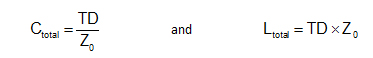
If you are looking for a refresher on this, it is all explained in Chapter 7 of my textbook, Signal and Power Integrity- Simplified, published by Prentice Hall.
In fact, a single L and C are very good approximations to an open or shorted transmission line. Figure 1 shows the comparison between the impedance looking into a transmission line with the far end open or shorted compared with the impedance of an ideal C or L given by the equations above.
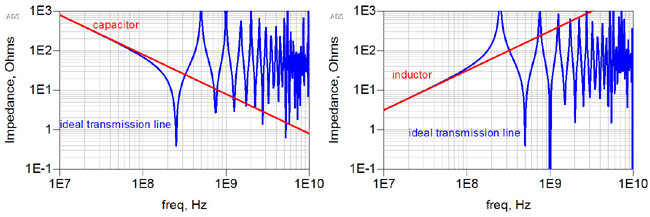
Figure 1. Input impedance of an ideal transmission line open and shorted at the far end compared with the equivalent C and L elements.
Notice that the impedance of an open transmission line is exactly the same as an ideal C at low frequency. Likewise, at low frequency, the input impedance of a transmission line shorted at the far end is exactly the same as an ideal inductor. But, it’s painfully clear that the C and L elements are a poor approximation to an ideal transmission line at higher frequency.
In each case, the approximation isn’t very accurate above about 200 MHz. This is for a TD = 1 nsec.
n-section Lumped Circuit Models
My students say, “but why not just use an LC circuit to model an interconnect? It’s a simple model and works at higher frequency.” Indeed, an LC section is a better than a single L or C. In Figure 2, we compare the input impedance of an LC model with an ideal transmission line model. At low frequency, the agreement is excellent. But not so good at higher frequency.
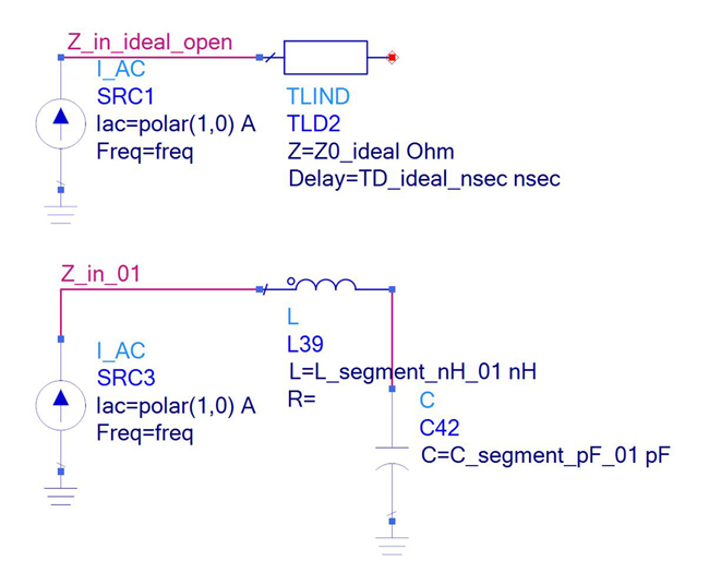

Figure 2. Circuit model comparing the input impedance of an ideal transmission line and an LC circuit and simulated impedances.
I offer extra credit to my students if they can tell me why the low impedance self-resonant frequency dips for these two models do not occur at the same frequency. If you think you know why, post a note in the comments section. The L and C values are taken directly from the equations above.
Then I hear, “why not use multiple LC sections, a ladder model to describe a transmission line? Won’t it look better at higher frequency?”
The Bandwidth an n-section LC Model as a Transmission Line Approximation
To get a better measure of the bandwidth of the model, the highest frequency at which we still have good agreement between the predictions of the ideal transmission line and the n-section LC model, we will switch to the transfer function, or S21. This is a direct measure of how much of the signal makes it through the interconnect.
In a matched impedance system, the transfer function of an ideal, lossless, transmission line is 1. All the signal gets through. But what about 1 section LC or 2 section or 4 or even 16 section LC model? These are basically low pass filter circuits. We would expect them to have a high frequency cut off, limiting their useful bandwidth as an approximation to a transmission line.
In Figure 3 we compare the transfer function, S21, of the ideal transmission line and a 1-section, 2-section, 4-section and 16-section LC model. In each case we scale the values of each L and C element so their total values match that of the ideal transmission line.

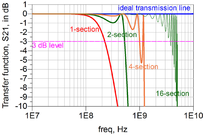
Figure 3. Example of the circuits used to simulate the transfer function for a 1-section, 2-section and 4-section LC circuit approximation to a transmission line and simulated transfer functions compared to an ideal transmission line.
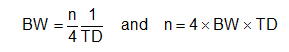
From this simulation it’s clear that the more sections we include in the n-section lumped model, the higher the bandwidth of the agreement with the transmission line model. If we use the rather arbitrary condition that the bandwidth is defined as the frequency at which the n-section model matches the ideal transmission line model by -3 dB, or 70%, then the bandwidth of an n-section model is roughly:
But, why do we care? When every simulator has an ideal transmission line element and most have ideal, lossy, coupled transmission line elements, and this model matches the simple C and L model at low frequency, and has the potential of much higher bandwidth than an n-section LC model, why shouldn’t the first choice to model any interconnect be an ideal transmission line?
After all, every interconnect is always a transmission line and the transmission line model of an interconnect will always be a higher bandwidth model than a lumped circuit approximation. The first model you should grab to model an interconnect should be a transmission line model.