
Last month, we discussed simple and affordable tools and instruments for characterizing radiated emissions, usually the number one electromagnetic compatibility (EMC) issue designers face. This month, we will tackle radiated immunity, which I have found to be tied for second with electrostatic discharge (ESD) in being at risk of EMC failures. I have used these techniques numerous times to identify and mitigate radiated immunity issues within a few hours. (We will address ESD troubleshooting next time.)
Most designers end up trying to troubleshoot radiated immunity at the compliance test lab. This makes sense because it takes a huge amount of expensive equipment, as well as a shielded semi-anechoic chamber, to perform this test. The drawback is that troubleshooting in this environment is time-consuming and expensive. It also greatly delays product introduction. Would it not be nice to move this troubleshooting process onto your own workbench?
Radiated immunity testing involves transmitting RF fields at certain specified V/m test levels and with either 1 kHz 80% AM (for commercial, consumer, and medical) or pulse modulated CW signals (military/aerospace or some medical products). The intent is to see whether the product under test is affected by nearby radio transmitters, cellular phones, or other wireless devices. Except for the U.S. and Canada, this is a worldwide requirement.
The essential instruments and techniques include an RF source, possibly a 3 to 5 watt wideband RF power amplifier, a set of near field probes, and an RF current probe. RF sources can include a "chattering relay," a small handheld walkie-talkie, an RF signal generator, or synthesized RF generator modules. I will describe each of these.
Bear in mind, full immunity testing is a lot tougher to perform on the bench, due to the expensive equipment specified and requirement to perform this in a semi-anechoic chamber. Therefore, the actual compliance test levels and frequency range according to EMC standards may not be accommodated. We are purely depending on intense locally generated fields to simulate the regular tests. To really ensure accurate radiated immunity levels, the product under test will have to be taken to a test lab.
Chattering Relay (AC or DC powered) – One way to create a source of broadband RF emissions is a “chattering relay” (shown in Figure 1). According to the standards, closely coupling the cable of the chattering relay to the product’s power cable is a rather rigorous immunity test. I find that simply holding the relay near your product circuitry should reveal any issues quickly.
Chattering relays are specified in some standards, such as SAE-J1113-12 (vehicular EMC), DO-160 (for aircraft), and used to be specified in the older MIL-STD-461C. You can make your own quite easily with a 120 VAC or 12/24 VDC relay that has heavy duty contacts.
I purchased a 120 VAC and a 12 VDC relay from Radio Shack (part number 2750044 or 2750043, respectively). I also bought a socket that fits either (part number 2750220), so that they may be easily replaced once the contacts wear out.

Figure 1. The schematic for the chattering relay.
The idea behind chattering relays is to wire the coil through one of the NC (normally closed) relay contacts — such that the relay is actuated momentarily until the contact opens —whereupon it closes again, repeating the process. This continues with a loud buzzing sound as the contacts continuously open and close. The inductance of the coil creates a 600 to 800 volt repeated arcing across the contacts.
This arcing at the contacts can create a tremendous amount of broadband EMI (up to 1 GHz, or higher), which may be inductively or capacitively coupled via the relay wiring to the equipment under test (EUT) power or I/O cabling. To couple the signal more strongly, try separating the conductors in the line cord.
Figure 2 shows the components required to make it, and Figure 3 shows the assembled relay with socket. Figure 4 is a screen capture of the EMI produced when closely coupled to a short antenna on the spectrum analyzer (upper trace). As you will see, the average amplitude is around 75 dBmV up to about 1 GHz. The flat display line is sitting at 85 dBmV. The lower trace is the ambient level. All traces have been placed in “max hold” mode.
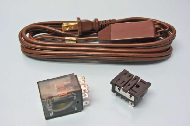
Figure 2. The components to make a DIY “chattering relay” are available online from Radio Shack or local electronics parts store.

Figure 3. The completed chattering relay. You will want to tape up the terminals for protection, if line powered.
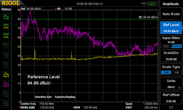
Figure 4. The spectral response of the chattering relay positioned near a short antenna on the analyzer input.
Family Radio Service (FRS) Walkie-Talkie - While you cannot beat a test lab for radiated immunity pre-compliance testing, there are several simple RF generators that will work well to at least give you a general feel for whether your circuitry is immune. One handy gadget I have used for a look at immunity is a personal handheld transceiver, such as the FRS (U.S./Canada) or PMR446 (EU) — see Figure 5. These may be purchased in most electronics stores for $20 to $30 for a pair.
While their transmitted frequency is limited to 462 to 467 MHz at 0.5 W power, it is still useful for inducing product failures when held very close to the circuitry or I/O cables, as is illustrated in Figure 6. I have performed many client troubleshooting investigations with nothing more than my FRS radio.
 Figure 5. A typical 0.5 W 465 MHz FRS two-way radio. Some other countries have similar license-free radios that may be used for simple radiated immunity testing.

Figure 6. Here, I am shown testing a bare digital board for radiated immunity. I am monitoring one of the outputs while transmitting on the FRS radio. The circuit appears to be working just fine.
RF Signal Generator – I have found that connecting a small H-field or E-field probe to a variable frequency RF generator capable of achieving at least +10 dBm (+20 dBm is better) power output allows you to zero in on specific circuitry or I/O cables (see Figure 7).
For very small products, connect the smallest H-field loop probe to the output. Tune the generator for one of the peak failure frequencies and you should be able to pinpoint the specific areas of susceptibility.

Figure 7. Here, we have set up an RF signal generator to one of the smallest Beehive Electronics H-field probes. This confines the RF field to a very limited area and helps you pinpoint areas of susceptibility.
RF Synthesizer - Several affordable RF synthesizers have been released in the last few years. Many of these have the desirable +10 to +20 dBm power output required for successful troubleshooting.
Windfreak Technologies SynthNV RF generator
The Windfreak model SynthNV is one of the smallest RF synthesizers that can produce +19 dBm (about 80 mW) over a range of 34 to 4,400 MHz and is priced at $599 (Figure 8).

Figure 8. The Windfreak Technologies SynthNV RF generator weighs just a few ounces and fits in your hand.
What caught my eye initially was that the generator could modulate (AM) the RF output perfectly for radiated immunity pre-compliance testing! But it will also pulse modulate the output – perfect for testing to the MIL-STD-461 and DO-160 standards! Its RF output level is sufficient to drive a near field probe with enough field strength to investigate susceptibilities within a product’s internal circuitry.
The generator is USB powered and can run with a Windows PC. It also includes an external power adapter input, so it can be programmed into a given state and then disconnected from the PC to run standalone as a local oscillator or RF generator.
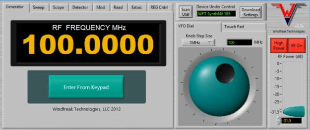
Figure 9. The basic user interface for the generator is based on National Instruments Labview.
The well-designed user interface (see Figure 9) is based on National Instruments Labview. The provided software includes the runtime engine for those who do not own the full Labview software. Figure 10 shows a CW signal with relatively low phase noise.

Figure 10. The typical RF output spectrum shows relatively low phase noise (measured at 100 MHz and 100 Hz RBW).

Figure 11. Typical 100 MHz fundamental and harmonic output of the generator. The third harmonic is about 10 dB down from the fundamental.
I believe the relatively high harmonic levels (see Figure 11) are because the output waveform below about 500 MHz is more of a square wave. Above 500 MHz, the signal converts to a sine wave. Though for the purposes of radiated immunity testing this is not that important, as the next highest harmonic (3rd harmonic) is 10 dB lower (1/10th the power). Still, if a cleaner signal is desired for other applications, filtering will be required.
In the usual troubleshooting or pre-compliance process I generally connect a near field probe (either H- or E-field) directly to the output of the generator and, while observing for disruptions, carefully sweep the probe around on the operating circuit board or cables of the product under test (shown in Figure 12). It is helpful if there is already compliance test failure data available, so the failing frequencies can be pre-tuned in advance. Otherwise, slowly sweep from 80 to 1000 MHz (or 2700 MHz depending on the standard). Once areas of circuit disruption are discovered, the power may be decreased in order to zero in on the offending circuitry more closely. The field levels at the tip of the probe were measured to be between 4 and 9 V/m between 34 and 1000 MHz – plenty of signal to induce most product failures.
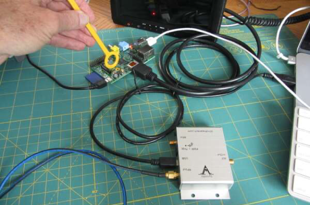
Figure 12. Probing a RaspberryPI embedded processor for radiated immunity.
Signal Hound VSG25A vector signal generator
The Signal Hound VSG25A (see Figure 13) runs from a standard USB 2.0 port and is adjustable from 100 to 2,500 MHz (in 1 Hz steps) with CW amplitudes adjustable from an advertised -40 to +10 dBm (my sample goes from -80 to +13 dBm). The phase noise is an acceptable -68 dBc/Hz (100 Hz) to -132 dBc/Hz (1 MHz). There are only two ports: the RF output (SMA connector) and USB-B connector.

Figure 13. For just $515, you receive the VG25A, a CD-ROM with software and USB cable. The user and programming manuals are available as downloads.
A small LED light indicates the unit is connected and communicating data. The unit will run from any Windows PC with a standard USB 2.0 port. The software is included on a CD-ROM and the USB cable is provided.
What is quite impressive is that this is truly a vector signal generator capable of modulating the RF output with AM, FM, pulse, multi-tone pattern, FSK, ASK, GFSK, OOK, MSK, GMSK, BPSK, QPSK, DQPSK, Pi/4DQPSK, OQPSK, 8-PSK, 16-PSK, 16-QAM, and 256-QAM. The VSG25A has way more capability than the typical EMC engineer requires, but would be invaluable for RF, wireless, and communications engineers.
The control screen (see Figure 14) for the VSG25A is simple and allows you to select CW (actually “Modulation = Off”) or any one of a couple dozen modulations (right side panel). For each modulation, there are settable parameters in the center of the screen. Frequency and amplitude are controlled in the top and RF on/off and modulation on/off are controlled in the bottom. The preset button allows you to define a preset configuration at power-up.
Useful modulations for EMC testing would include 1 kHz AM at 80% modulation for consumer, industrial, and medical products, 1 kHz pulse modulation for military and aeronautical systems, and a newer 217 Hz for medical products. Both the modulation frequency and percent modulation may be entered directly within the control panel.

Figure 14. The control screen for the Signal Hound VSG25A allows you to select CW or any one of a dozen modulations. This is the set up for AM modulation at 100 MHz.
CW and AM Mode - Observing the CW signal at 100 MHz (see Figure 15), we see a fairly reasonable phase noise, but with a few very low-level spurs – most of which are about -70 dBc or less. The amplitude accuracy is well within the specified +/-1.5 dB. Figure 16 shows a time domain look at the modulated waveform.
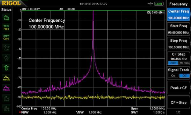
Figure 15. A screen capture of a CW signal at 100 MHz and an amplitude of zero dBm. The resolution bandwidth was set to 1 kHz in order to observe the skirts better.
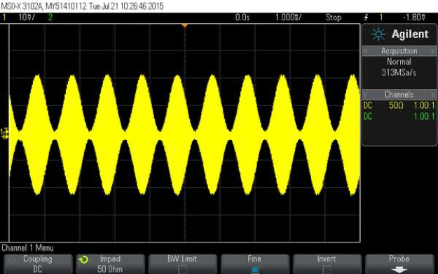
Figure 16. An example of a 1 kHz 80% modulated AM wave. The VSG25A can also modulate the wave with a triangle, square, or ramp.
For radiated immunity testing, the control screen provides a frequency step mode (Step/Sweep), where start, stop, and step frequencies may be defined, as well as dwell time in ms.
Pulse Mode - Pulses may be programmed from 6 ns to 25 ms in width with a period from 12 ns to 1 sec. This mode would be useful for MIL-STD-461 or DO-160 testing to simulate radar susceptibilities. Figure 17 shows the pulsed waveform in the time domain.

Figure 17. Above is a pulse modulated waveform using the default settings.
The VSG25A is just $515 and includes the software on CD-ROM, as well as the USB cable. The user and programming manuals are free downloads from Signal Hound’s website.
Tekbox Modulated Broadband RF Amplifiers
If you have a spectrum analyzer with a tracking generator, it is possible to use this as your RF source. Since most tracking generator outputs are limited to -10 to zero dBm, the signal will generally need to be boosted to at least +15 to +20 dBm. A modulated RF power amplifier may be just what you need to create a controlled and variable frequency source of RF for localized immunity testing. These modulated amplifiers may also be used with a conventional RF generator to boost the output power.
Tekbox is starting to manufacture such a line of modulated broadband RF amplifiers (see Figure 18). These are designed to work in conjunction with the tracking generator on a spectrum analyzer. The amplifier includes modulation controls so that when fed with a low-level signal from the spectrum analyzer's tracking generator, or other RF source, it will produce CW, 1 kHz 80% modulated AM, 1 kHz pulse, and 217 Hz pulse (for GSM phone testing). Output powers range from +22 to +47 dBm, which should be plenty to produce a very intense localized RF field.
 Figure 18. Tekbox makes a line of broadband modulated RF amplifiers for use in radiated emissions testing. Their model TBMDA3 can produce up to +45 dBm.
The Vectawave VBM2500-3 RF amplifier
The Vectawave model VBM2500-3 produces up to 3W output (at less than 1 dB gain compression) from 10 to 2,500 MHz at a specified minimum of 38 dB gain.
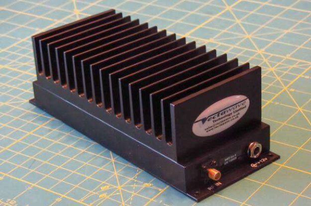
Figure 19. The Vectawave VBM2500-3 RF amplifier claims up to 3W output from 10 to 2500 MHz.
The Vectawave VBM2500-3 is a relatively small, solidly built, 3 W amplifier (see Figure 19). It is rated for full shorted to open loads and appears stable when used with any type near field probe. Under near-continuous use in the open, the unit gets warm to the touch, but not to the point where forced air circulation is required. The small size and 12 V power requirement allows for easy portable/mobile operation. The price is $3,400.
Summary
The ability to perform localized radiated immunity testing is a concept rarely taught. I have been able to solve several RF immunity issues with nothing more than a handheld personal walkie-talkie or by producing an intense RF field using an RF generator feeding a near field probe.
I have experienced several cases where clients have tried troubleshooting RF immunity issues for weeks, going back and forth to the test lab, and then I am called in to find the sensitive nodes in their circuits within an hour or two. This is a very powerful technique!
References
- Assembling an EMC Troubleshooting Kit: Radiated Emissions, Signal Integrity Journal, February 2022.
- Inexpensive Radiated Immunity Pre-Compliance Testing
- Create Your Own EMC Troubleshooting Kit (Volume 1)