

Most DC/DC converters and switching voltage regulators use filter inductors. The inductors we see range from about 100 nH up to a few tens of microHenries (uH). These inductors operate with DC current through them, so it’s common to measure the inductors with DC bias. We produce two bias units to support these measurements, one for up to about 5 uH and 125 Amps and another that can provide bias up to 20 Amps and a few hundred uH. I was recently asked how to measure a 25 mH inductor with DC bias. That is far beyond the dynamic range of our devices for biased measurements. Without DC bias, this measurement is simple, and we don’t need anything special to do that, so the limitation is really the DC bias.
There are precision analyzers available that can do that, and Wayne Kerr comes to mind. However, if you aren’t making these measurements routinely, the price tag of an analyzer might be cost-prohibitive. But maybe you need to make the measurement NOW; it can be done, and here is how I did it.
What makes this difficult is that the inductance is measured by applying an AC voltage at a modulation frequency and dividing the AC voltage by the AC current. The AC current is very tiny, due to the very high inductance value. The DC bias is much greater, so there are two issues to deal with. One is that we need to sense a very small current, which requires a very low noise current probe. The other is the large dynamic range of the DC current to the AC current. Both issues strain even the best frequency response analyzer (FRA)/vector network analyzer (VNA) when bias is applied.
This measurement is made in two parts. In the first part, we measure a reference inductor in the range that we know we can accurately measure. For this example, I used a 100 uH inductor, fabricated by my friends at Standex Electronics. This inductor is wound on a Magnetics, Inc. Edge® Core to achieve the flattest inductance vs. DC bias characteristics. The reference inductor must provide a stable inductance value without significant DC bias droop at the larger inductor’s (DUT’s) target DC bias current.
The reference inductor was measured with DC bias using the J2121A in accordance with the methods published in this article. The impedance, measured at 0.1 Amps and 20 Amps, shown in Figure 1, confirms the inductance is stable up to 20 Amps. This is well above the DUT’s operating current. The measurement starts to get noisy above 25 Ohms, that is due to the dynamic range of the J2121A measurement, and in particular, the internal hall effect current monitor. A bit more dynamic range could be obtained using an external passive current probe. This is also why we cannot measure the large value inductor directly using this method.
It is essential to measure a known part before measuring an unknown part to validate the setup and test methodology. The known part needs to be of the same or similar magnitude as our DUT to provide reasonable validation. Standex Electronics manufactures a line of high inductance pot-cores. I will use their RL-7300-5-27, a 27 mH inductor, to validate our measurement setup. This is very close to the customer measurement and allows me to share this method while protecting my customer’s proprietary data.
Once we have the value of the reference inductor, we can use this value in all our future measurements within the operating current range of the reference, or at least 20 Amps for this inductor.

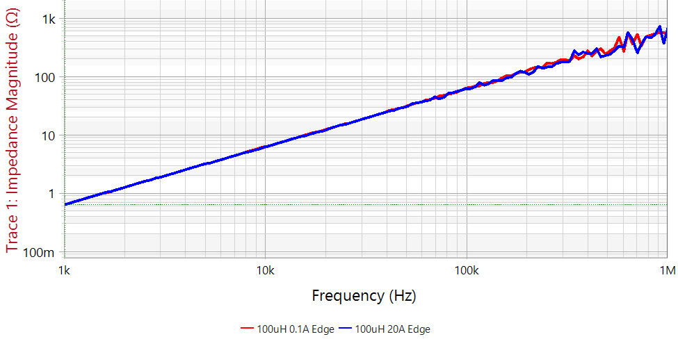 Figure 1. The reference inductor provides a stable 100 uH without significant droop between 0.1 Amps and 20 Amps. The measurement starts to get noisy above about 25 Ohms due to the dynamic range, established largely by the internal hall effect current monitor.
Now, here is the trick. We can accurately measure the reference inductor, and we know its value. Rather than measuring inductance, we will measure a voltage ratio. Most FRAs, including the Bode 100 I use here, have great dynamic range for voltage ratios.
A voltage divider is created using the reference inductor in the bottom of the divider and the sample to be tested in the top of the divider, as shown in Figure 2. The voltage divider can be DC biased and modulated using the J2121A. Rather than measuring inductance, we measure the voltage ratio of the injection signal to the tap.
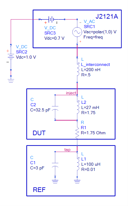 Figure 2. The J2121A provides DC bias current and signal modulation through both the reference inductor and the DUT. The voltage ratio inject/tap is measured using the FRA.
Calculating the voltage divider ratio and solving for the DUT, results in
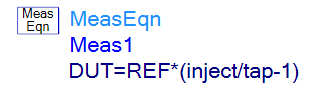
Figure 3. The reference inductor is shown connected to the 27 mH pot-core inductor and the J2121A for bias.
Measuring this circuit results in the tap voltages for various DC bias currents shown in Figure 4.

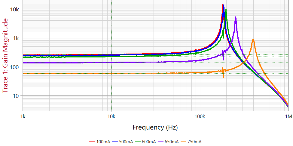 Figure 4. The measured voltage ratio is shown here to be 264 at 100 mA and dropping a few percent at 500 mA before dropping rapidly above 500 mA. The resonant frequency of approximately 174 kHz is also preserved in the measurement.
The reference inductor and the measured ratio are transformed to obtain the inductance of the DUT, which is very close to the known value of 27 mH. Beginning with the Bode Analyzer Suite version 3.25, this equation can be performed internal to the Bode 100: 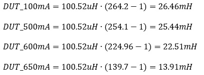
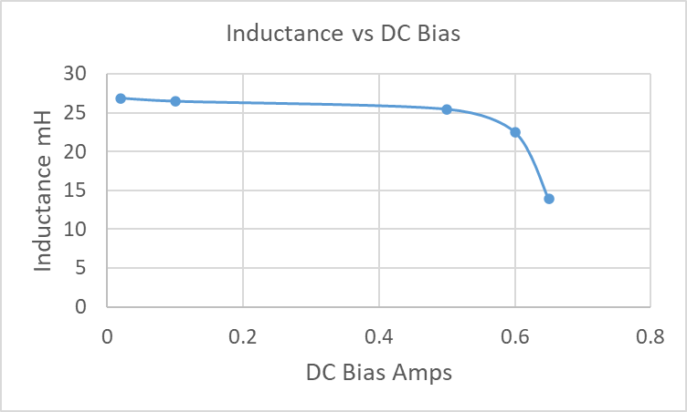 Figure 5. Inductance vs. DC Bias graphed from the measured data.
Using a known stable reference inductance as the bottom element in a voltage divider, the FRA can measure very large inductance values with DC bias added and preserving the self-resonant frequency.
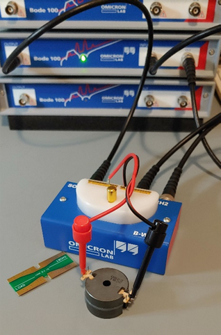
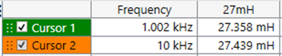
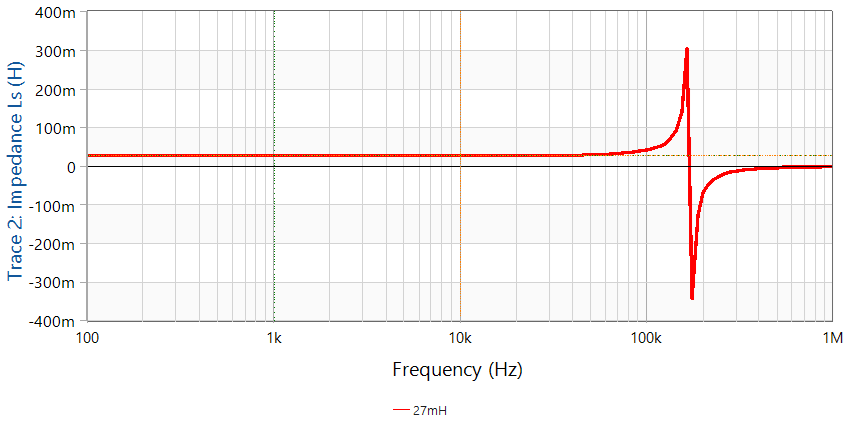
Figure 6. The inductor is measured using a B-WIC impedance adapter without DC bias. The inductor measures 27.4 mH and the SRF is 171 kHz. This is a well calibrated traditional measurement. The only shortcoming is that it cannot be used with DC bias.
This measurement can be sensitive to the impedance and compensation of the two voltage probes used for the measurement. A good tip is to measure the inductance, without DC bias, using a conventional method. Measuring our 27 mH inductor using a B-WIC impedance adapter is shown in Figure 6. The biased measurement can then be scaled, if necessary, to match this value at low current.