

This extreme measurement example is from a DesignCon 2020 paper, titled “A Method for Dynamic Load Current Testing with a Benchtop Power Supply” [1]. My good friend and colleague, Heidi Barnes, from Keysight, performed the bulk of this seemingly impossible effort. The goal was to determine the dynamic current of the FPGA by measuring the AC current in an external voltage regulator module (VRM) using a transformation of the PCB S-parameters and the simultaneous measurement of the AC voltages across the PDN.
While there are a few different challenges presented here, the first is that on the PCB there is not an accessible point to measure the VRM current. Rather, an external DC-DC converter module was soldered to the PCB using wide copper foil to minimize the inductance of the connection. Since most current probes are inductive, they would impact the measurement. So, a PEM Rogowski current probe was used, despite the noisy nature of this type of probe. This external DC-DC converter and Rogowski probe setup is shown in Figure 1.
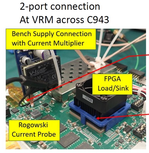
Figure 1 The external VTM DC-DC converter module is seen, soldered to the PCB using wide copper foil and the Rogowski probe is soldered around the positive foil power lead.
Samples of the decoupling capacitors were measured and modeled and loaded into Keysight Pathwave ADS. The S-parameters were extracted using the ADS PIPRO simulator, and a model of the setup was constructed, including a measurement of the inductance of the VRM at the PCB point of contact.
The recommendation to measure something you know first is applied here within the simulator. A “known” FPGA dynamic current is applied to the PDN model, and then the resulting VRM and voltage data is used in a second simulation with the model to synthesize the dynamic current. The synthesized result is compared directly with the applied dynamic current of the first simulation. The comparison is shown in Figure 2.
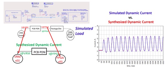
Figure 2 A dynamic current is applied at the FPGA and the VRM data is used to synthesize the dynamic current that was applied. The results show excellent correlation.
An added benefit is that by having the correlated methodology, additional details can be obtained, in this case one additional detail is a 30MHz package resonance, shown in Figure 3.
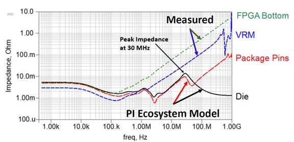
Figure 3 The resulting data and simulation reveal a 30MHz package resonance, shown here.
The resonance is confirmed by simultaneously toggling 400,000 flip-flop registers in the FPGA. Toggling them at 30MHz results in an average VRM current of 2.5 Amps and toggling the same number of flip-flops at 200 MHz results in an average VRM current of 13.5 Amps. Despite the lower 30 MHz average current, the voltage and current ripple is larger than the voltage and current ripple at 200 MHz with the higher average current. The results at 30 MHz and at 200 MHz are seen in Figure 4.
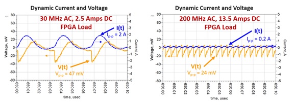
Figure 4 The excursion resulting from 400,000 flip-flops at 30MHz is larger than the result at 200MHz, despite the 200MHz result having a much higher average current.
This example was originally presented at DesignCon 2021.
References
[1] Heidi Barnes, Jack Carrel, Steven M. Sandler, A Method for Dynamic Load Current Testing with a Benchtop Power Supply, DesignCon 2020