
Impedance by any other name…
In more than 30 years of teaching signal integrity, I find the most confusing topic for engineers, even those working in the field for years, is the question of what is the impedance of a transmission line?
The reason it is so confusing is that there are actually five types of impedance, and, if we are not careful providing the qualifier, I may be talking one type of impedance and you are thinking another type of impedance.
Here are the five types of impedance, as they apply to a uniform transmission line, with their qualifiers.
The instantaneous impedance is the impedance a signal sees each step along the way as it propagates down a uniform transmission line, as illustrated in Figure 1. If the transmission line is uniform in cross section, the instantaneous impedance will be constant.
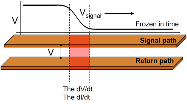
Figure 1. A signal propagating on a uniform transmission line, sees an instantaneous impedance each step along the way.
The characteristic impedance is the one value of instantaneous impedance that “characterizes” the uniform transmission line.
The input impedance of the transmission line in the frequency domain is the impedance, looking between the signal and return path, at the beginning of the transmission line, in steady state, at any single frequency at a time.
The input impedance of the transmission line in the time domain is the impedance, looking between the signal and the return path, at the beginning of the transmission line, when we apply a step voltage signal into the transmission line. The input impedance, in the time domain is not constant. It varies with time, and varies depending on the source impedance, rise time of the signal and time delay of the transmission line.
The surge impedance of the transmission line is an older term, not used much today, which is the input impedance of the transmission line in the time domain, during the initial “surge time” the signal is traveling down the transmission line before, it reflects back to the source.
When we refer to just “the impedance” of a transmission line, which one do we mean?
Figures of merit for a uniform, lossless transmission line
There are only two terms that describe the electrical properties of a uniform, lossless transmission line, a characteristic impedance (Z0) and a time delay (TD). From these two terms, all the other impedances can be calculated.
When we just refer to “the impedance” of a transmission line, most of the time, I think we mean the characteristic impedance of the line. This is the one value of instantaneous impedance a signal would see as it propagates down the line.
But I also think we often want to know the input impedance of the transmission line a driver sees when it launches a signal into the transmission line. This is also the same question as what is the load the transmission line places on the driver circuit? The challenge answering this question is that “it depends.”
The input impedance of a transmission line, in the time domain, is not an intrinsic figure of merit, but changes with time and depends on the source impedance of the driver and the termination at the other end of the line.
The Input Impedance of a Transmission Line
A quick glance at the equivalent circuit of a driver driving a uniform line terminated at its far end, shown in Figure 2, shows the two extreme limits: at the initial time and after a long time. Getting the impedances in-between is complicated and requires a circuit simulation.
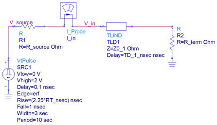
Figure 2. Circuit diagram of a transmission line driven by a source resistance with a termination impedance, Keysight's ADS.
From the circuit diagram, the initial impedance we see looking into the transmission line is the instantaneous impedance of the line. This is the same as the surge impedance and the same as the characteristic impedance.
The signal launched into the line will travel down the line to the termination, where it will reflect and make its way back to the source. The reflected signal will appear back at the source in a round trip time, which is 2 x the time delay (TD). Before 2 x TD, no information about the reflections and the end of the line can appear at the beginning of the line.
In the first 2 x TD nsec the input impedance we see looking into the transmission line is just the characteristic impedance.
If we wait a day, and all the reflections have happened and they have all died down, the impedance we see looking into the transmission line will be its termination resistance. If it is open, we will see an open looking into the front of the transmission line. If the termination is 25 Ohms, we will see 25 Ohms at the input to the line.
Between the time 2 x TD and a day, the impedance we see looking into the beginning of the line will change in some complicated way due to all the reflections back and forth. The impedance profile we see depends on the rise time, the source impedance and the termination impedance, properties that have nothing to do with the intrinsic properties of the transmission line.
In general, it is tough to calculate the impedance profile over time looking into the front of the transmission line, but it is easy to simulate it using the circuit above. We calculate the input impedance based on the definition of impedance as the V/I.
In the circuit above, I added a current meter so we can measure the current going into the line, and we simulate the voltage across the line at the input. When the rise time is short compared to the TD, we can resolve each reflection by looking at the input.
In this example, the TD = 1 nsec and we look for 20 nsec. There is plenty of time for all the reflections to die down. The rise time is 0.5 nsec, which is shorter than 2 x TD, so we can resolve each reflection.
I chose the source resistance as 100 Ohm, and the termination of the line as 1000 Ohms, high compared to the 50 Ohm characteristic impedance of the line, but not too high.
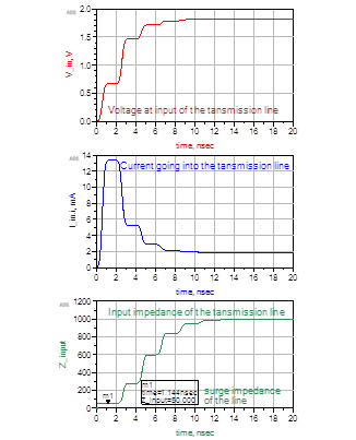
Figure 3. The voltage at the input, the current going into the line and the calculated input impedance of the transmission line using Keysight’s ADS.
Conclusion
No matter what the source impedance is, no matter what the termination is, the initial impedance we will measure at the beginning of the line will always be the characteristic impedance of the line. But, after 2 x TD, the input impedance of the line will change, unless the termination resistance = the characteristic impedance.
When we ask “what is the impedance of the line?” the easy answer is, the characteristic impedance. When we want to know the impedance of the line the driver sees, the answer is, “it depends.” The initial value is always the characteristic impedance. The final value is always the termination of the line. But how it gets from the initial to the final depends on all the details.
This is why it is not so simple an answer. And, this is why reflections in transmission lines can generate a slew of problems, in addition to the reflected signal rattling around.
Also See: